EXHAUST MANIFOLD > INSTALLATION |

for Preparation Click here
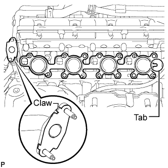
| 1. INSTALL EXHAUST MANIFOLD SUB-ASSEMBLY RH |
Install a new gasket to the cylinder head and a new gasket to the No. 2 air tube.
- HINT:
- Install the exhaust manifold gasket with the gasket tab facing toward the front of the engine.
- Install the air tube gasket with the gasket's claws facing the tube side.
 |
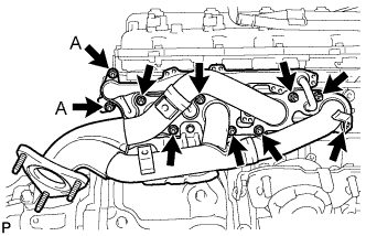
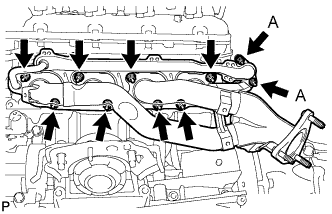
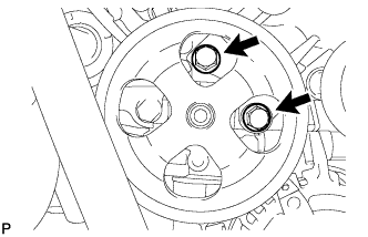
Temporarily install the exhaust manifold and then uniformly tighten 8 new nuts that are not labeled A. Then tighten the new nuts labeled A in the illustration.
- Torque:
- for nut A:
- 10 N*m{ 102 kgf*cm , 7 ft.*lbf }
- except nut A:
- 21 N*m{ 214 kgf*cm , 15 ft.*lbf }
 |
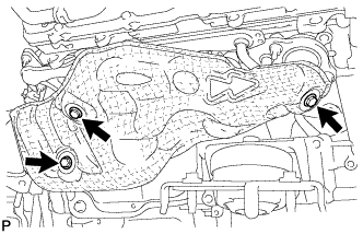
| 2. INSTALL NO. 1 EXHAUST MANIFOLD HEAT INSULATOR |
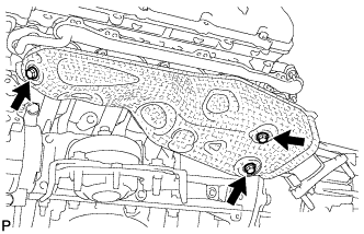
Install the heat insulator with the 3 bolts.
- Torque:
- 10 N*m{ 102 kgf*cm , 7 ft.*lbf }
 |
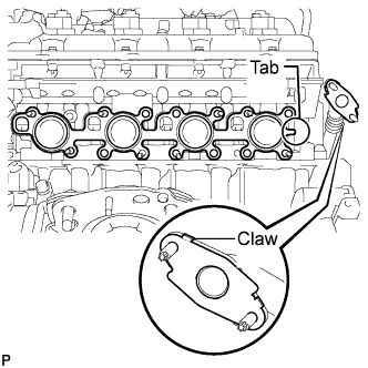
| 3. INSTALL EXHAUST MANIFOLD SUB-ASSEMBLY LH |
Install a new gasket to the cylinder head and a new gasket to the No. 3 air tube.
- HINT:
- Install the exhaust manifold gasket with the gasket tab facing toward the rear of the engine.
- Install the air tube gasket with the gasket's claws facing the tube side.
 |
Temporarily install the exhaust manifold and then uniformly tighten 8 new nuts that are not labeled A. Then tighten the new nuts labeled A in the illustration.
- Torque:
- for nut A:
- 10 N*m{ 102 kgf*cm , 7 ft.*lbf }
- except nut A:
- 21 N*m{ 214 kgf*cm , 15 ft.*lbf }
 |
| 4. INSTALL NO. 2 EXHAUST MANIFOLD HEAT INSULATOR |
Install the heat insulator with the 3 bolts.
- Torque:
- 10 N*m{ 102 kgf*cm , 7 ft.*lbf }
 |
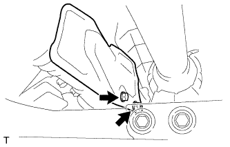
| 5. INSTALL NO. 2 STEERING INTERMEDIATE SHAFT SUB-ASSEMBLY |
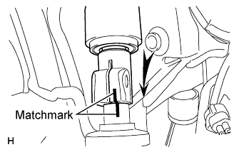
Align the matchmarks and insert the No. 2 intermediate shaft into the intermediate shaft.
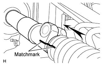 |
Align the matchmarks and insert the No. 2 intermediate shaft into the power steering gear.
 |
Install the 2 bolts.
- Torque:
- 35 N*m{ 357 kgf*cm , 26 ft.*lbf }
| 6. INSTALL FRONT EXHAUST PIPE ASSEMBLY |
Install a new gasket and the front exhaust pipe to the exhaust manifold RH with 3 new nuts.
- Torque:
- 54 N*m{ 554 kgf*cm , 40 ft.*lbf }
Install a new gasket and the front exhaust pipe to the center exhaust pipe with the 2 bolts.
- Torque:
- 48 N*m{ 489 kgf*cm , 35 ft.*lbf }
Connect the air fuel ratio sensor connector.
Connect the heated oxygen sensor connector and 2 clamps.
| 7. INSTALL FRONT NO. 2 EXHAUST PIPE ASSEMBLY (except Regular Cab Standard Deck) |
Connect the front No. 2 exhaust pipe to the exhaust pipe support.
Install a new gasket and the front No. 2 exhaust pipe to the exhaust manifold LH with 3 new nuts.
- Torque:
- 54 N*m{ 554 kgf*cm , 40 ft.*lbf }
Install a new gasket and the front No. 2 exhaust pipe to the center exhaust pipe with the 2 bolts.
- Torque:
- 48 N*m{ 489 kgf*cm , 35 ft.*lbf }
Connect the air fuel ratio sensor connector.
Connect the heated oxygen sensor connector.
| 8. INSTALL FRONT NO. 2 EXHAUST PIPE ASSEMBLY (for Regular Cab Standard Deck) |
Install a new gasket and the front No. 2 exhaust pipe to the exhaust manifold LH with 3 new nuts.
- Torque:
- 54 N*m{ 554 kgf*cm , 40 ft.*lbf }
Install a new gasket and the front No. 2 exhaust pipe to the front No. 3 exhaust pipe with the 2 bolts and 2 new nuts.
- Torque:
- 48 N*m{ 489 kgf*cm , 35 ft.*lbf }
Connect the air fuel ratio sensor connector.
Connect the heated oxygen sensor connector.
| 9. INSTALL FRONT PROPELLER SHAFT ASSEMBLY (for 4WD) |
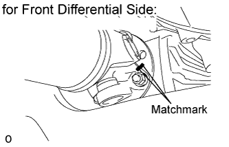 |
for Front Differential Side:
Align the matchmarks on the differential and propeller shaft flange.
Install the propeller shaft with the 4 washers and 4 nuts.
- Torque:
- 80 N*m{ 816 kgf*cm , 59 ft.*lbf }
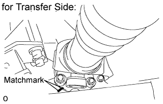
for Transfer Side:
Align the matchmarks on the transfer and propeller shaft flange.
Connect the propeller shaft with the 4 washers and 4 nuts.
- Torque:
- 80 N*m{ 816 kgf*cm , 59 ft.*lbf }
 |
| 10. INSTALL PROPELLER SHAFT HEAT INSULATOR (for 4WD) |
Install the heat insulator with the 2 bolts.
- Torque:
- 16 N*m{ 163 kgf*cm , 12 ft.*lbf }
 |
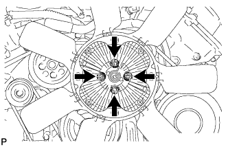
| 11. CONNECT COOLER COMPRESSOR ASSEMBLY |
Install the cooler compressor with the 2 stud bolts.
- Torque:
- 10 N*m{ 102 kgf*cm , 7 ft.*lbf }
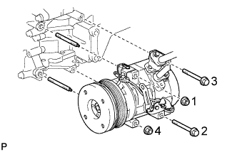 |
Install the 2 bolts and 2 nuts.
- Torque:
- 25 N*m{ 250 kgf*cm , 18 ft.*lbf }
- NOTICE:
- Tighten the bolts and nuts in the order shown in the illustration to install the cooler compressor.
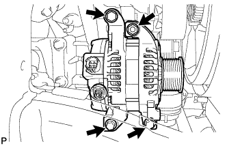
| 12. INSTALL GENERATOR ASSEMBLY |
Install the generator with the 3 bolts and nut.
- Torque:
- 43 N*m{ 439 kgf*cm , 32 ft.*lbf }
 |
Connect the generator connector.
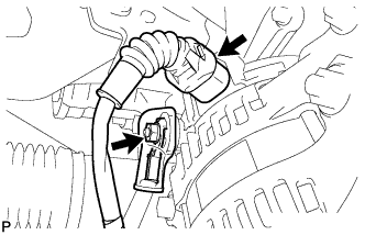 |
Connect the generator wire with the nut.
- Torque:
- 9.8 N*m{ 100 kgf*cm , 87 in.*lbf }
Install the terminal cap.
Install the harness bracket to the generator with the bolt.
- Torque:
- 31 N*m{ 316 kgf*cm , 23 ft.*lbf }
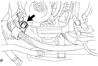 |
| 13. CONNECT VANE PUMP ASSEMBLY |
- HINT:
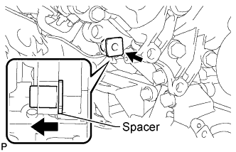 |
- Before performing the following procedures, move the spacer until the vane pump can be installed.
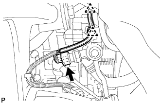
Connect the vane pump to the timing chain cover with the 2 bolts.
- Torque:
- 28 N*m{ 286 kgf*cm , 21 ft.*lbf }
 |
Attach the 2 clamps and connect the power steering oil pressure switch connector.
 |
| 14. INSTALL ENGINE OIL LEVEL DIPSTICK GUIDE |
Apply a light coat of engine oil to a new O-ring.
Install the O-ring to the guide.
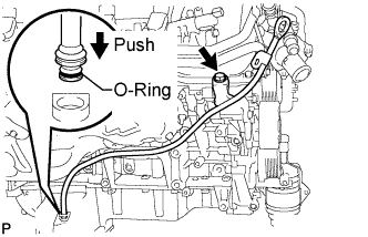 |
Install the dipstick guide with the bolt.
- Torque:
- 10 N*m{ 102 kgf*cm , 7 ft.*lbf }
Install the dipstick.
| 15. INSTALL FAN SHROUD |
Install the fan pulley to the fan bracket.
Place the shroud together with the coupling fan between the radiator and engine.
- NOTICE:
- Be careful not to damage the radiator core.
Temporarily install the fluid coupling fan to the fan bracket with the 4 nuts. Tighten the nuts as much as possible by hand.
Attach the shroud's claws to the radiator as shown in the illustration.
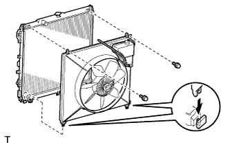 |
Install the shroud with the 2 bolts.
- Torque:
- 6.5 N*m{ 66 kgf*cm , 58 in.*lbf }
Connect the reservoir hose to the upper radiator tank.
Install the fan and generator V-belt.
Tighten the 4 nuts of the fluid coupling fan.
- Torque:
- 21 N*m{ 214 kgf*cm , 15 ft.*lbf }
 |
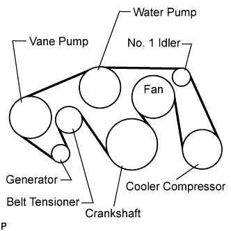
| 16. INSTALL FAN & GENERATOR V BELT |
Set the V belt onto every part.
 |
While turning the belt tensioner counterclockwise, remove the pin.
- NOTICE:
- Make sure that the V belt is properly set to each pulley.
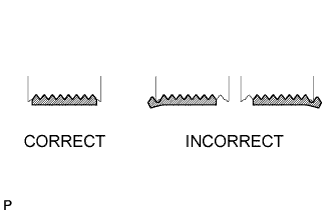
After installing the belt, check that it fits properly in the ribbed grooves.
- HINT:
- Make sure to check by hand that the belt has not slipped out of the grooves on the bottom of the pulley.
 |
| 17. CONNECT OUTLET RADIATOR HOSE |
| 18. CONNECT INLET RADIATOR HOSE |
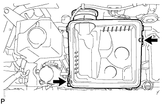
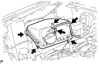
| 19. INSTALL AIR CLEANER ASSEMBLY |
Install the air cleaner case with the 2 bolts.
- Torque:
- 5.0 N*m{ 51 kgf*cm , 44 in.*lbf }
 |
Install the air cleaner element onto the air cleaner case.
Install the air cleaner cap.
Fasten the 4 hook clamps.
Connect the MAF meter connector.
Attach the wire harness clamp.
 |
| 20. INSTALL AIR CLEANER HOSE ASSEMBLY |
Install the air cleaner hose with the 2 clamps.
- Torque:
- 4.0 N*m{ 41 kgf*cm , 35 in.*lbf }
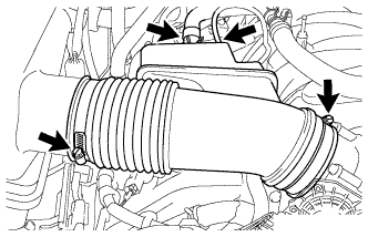 |
Connect the vacuum hose and ventilation hose.
| 21. CONNECT CABLE TO NEGATIVE BATTERY TERMINAL |
| 22. ADD ENGINE COOLANT |
Add engine coolant.
Standard capacity: Item Specified Condition w/ Trailer Towing System 13.0 liters (13.7 US qts, 11.4 Imp. qts) w/o Trailer Towing System 12.1 liters (12.8 US qts, 10.6 Imp. qts) - NOTICE:
- Do not substitute plain water for engine coolant.
- HINT:
- TOYOTA vehicles are filled with TOYOTA SLLC at the factory. In order to avoid damage to the engine cooling system and other technical problems, only use TOYOTA SLLC or similar high quality ethylene glycol based non-silicate, non-amine, non-nitrite, non-borate coolant with long-life hybrid organic acid technology (coolant with long-life hybrid organic acid technology is a combination of low phosphates and organic acids).
- Please contact your Toyota dealer for further details.
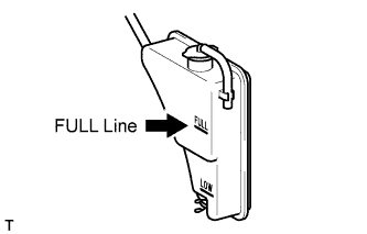
Slowly pour coolant into the radiator reservoir until it reaches the FULL line.
 |
Install the reservoir cap.
Press the inlet and outlet radiator hoses several times by hand, and then check the coolant level. If the coolant level is low, add coolant.
Install the radiator cap.
Start the engine and warm it up until the thermostat opens.
- HINT:
- The thermostat opening timing can be confirmed by pressing the radiator inlet hose by hand, and checking when the engine coolant starts to flow inside the hose.
Maintain the engine speed at 2000 to 2500 rpm.
- NOTICE:
- Make sure that the radiator reservoir still has some coolant in it.
- Pay attention to the needle of the water temperature meter. Make sure that the needle does not show an abnormally high temperature.
- If there is not enough coolant, the engine may burn out or overheat.
- Immediately after starting the engine, if the radiator reservoir does not have any coolant, perform the following: 1) stop the engine, 2) wait until the coolant has cooled down, and 3) add coolant until the coolant is filled to the FULL line.
- Run the engine at 2000 rpm until the coolant level has stabilized.
Press the inlet and outlet radiator hoses several times by hand to bleed air.
- CAUTION:
- Wear protective gloves.
- Be careful as the radiator hoses are hot.
- Keep your hands away from the fan.
Stop the engine, and wait until the engine coolant cools down to ambient temperature.
- CAUTION:
- Do not remove the radiator cap while the engine and radiator are still hot. Pressurized, hot engine coolant and steam may be released and cause serious burns.
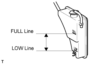
Check that the coolant level is between the FULL and LOW lines.
If the coolant level is below the LOW line, repeat all of the procedures above.
If the coolant level is above the FULL line, drain coolant so that the coolant level is between the FULL and LOW lines.
 |
| 23. INSPECT FOR COOLANT LEAK |
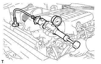 |
- CAUTION:
- Do not remove the radiator cap while the engine and radiator are still hot. Pressurized, hot engine coolant and steam may be released and cause serious burns.
Fill the radiator with coolant and attach a radiator cap tester.
Warm up the engine.
Using the radiator cap tester, increase the pressure inside the radiator to 118 kPa (1.2 kgf/cm2, 17 psi), and check that the pressure does not drop.
If the pressure drops, check the hoses, radiator and water pump for leaks. If no external leaks are found, check the heater core, cylinder block and head.
| 24. INSPECT FOR EXHAUST GAS LEAK |
| 25. INSTALL FRONT FENDER APRON SEAL REAR LH |
Install the fender apron seal with the 5 clips.
| 26. INSTALL FRONT FENDER APRON SEAL LH |
Install the fender apron seal with the 6 clips.
| 27. INSTALL FRONT FENDER APRON SEAL REAR RH |
Install the fender apron seal with the 5 clips.
| 28. INSTALL FRONT FENDER APRON SEAL RH |
Install the fender apron seal with the 6 clips.
| 29. INSTALL NO. 1 ENGINE UNDER COVER |
Hook the engine under cover to the vehicle body as shown in the illustration.
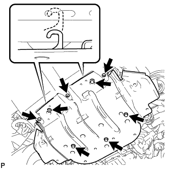 |
Install the 3 screws and 5 bolts.
- Torque:
- for bolt:
- 29 N*m{ 296 kgf*cm , 21 ft.*lbf }
- for screw:
- 5.4 N*m{ 55 kgf*cm , 48 in.*lbf }
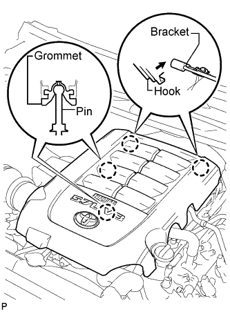
| 30. INSTALL V-BANK COVER SUB-ASSEMBLY |
Attach the 2 V-bank cover hooks to the bracket. Then align the 2 V-bank cover grommets with the 2 pins, and press down on the V-bank cover to attach the pins.
 |