STEERING GEAR > REASSEMBLY |

for Preparation Click here
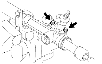
- NOTICE:
- When installing, coat the parts indicated by the arrows with power steering fluid (Click here).
| 1. INSTALL RACK STEERING PISTON RING |
 |
Coat a new O-ring with power steering fluid and install it onto the power steering rack.
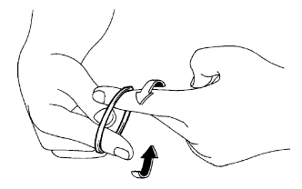
Expand a new piston ring with your fingers.
- NOTICE:
- Be careful not to over expand the rack steering piston ring.
Coat a new piston ring with power steering fluid.
Install the piston ring onto the power steering rack, and position it with your fingers.
 |
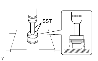
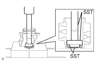
| 2. INSTALL POWER STEERING CYLINDER TUBE OIL SEAL |
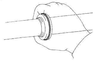
Coat a new cylinder tube oil seal lip with power steering fluid.
Using SST and a press, install the cylinder tube oil seal.
- SST
- 09950-60010
(09951-00280, 09951-00480, 09952-06010)
09950-70010 (09951-07360)
- NOTICE:
- Make sure that the cylinder tube oil seal is installed facing in the correct direction.
- Take care not to reverse the cylinder tube oil seal direction when installing.
 |
| 3. INSTALL POWER STEERING RACK |
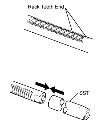 |
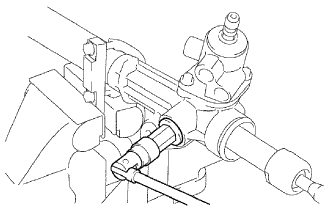
Install SST onto the power steering rack.
- SST
- 09631-20111
- HINT:
- If necessary, scrape the burrs off the power steering rack teeth end and burnish.
Coat SST with power steering fluid.
Install the power steering rack into the rack housing.
Remove SST.
| 4. INSTALL POWER STEERING RACK BUSH |
 |
Using SST and a press, install a new rack bush oil seal onto the rack bush.
- SST
- 09950-60010
(09951-00440)
09950-70010 (09951-07100)
- NOTICE:
- Make sure that the rack bush oil seal is installed facing the correct direction.
Coat a new O-ring with power steering fluid and install it onto the rack bush.
To prevent the rack bush oil seal lip from being damaged, wind vinyl tape around the rack end and apply power steering fluid.
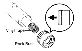 |
Install the rack bush onto the power steering rack.
| 5. INSTALL CYLINDER END STOPPER |
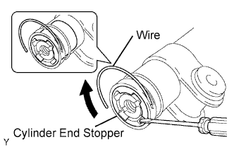 |
Align the installation hole for the wire of the cylinder end stopper with the slot of the rack housing.
Install a new wire into the cylinder end stopper.
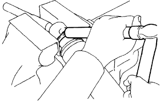
Using a screwdriver, turn the cylinder end stopper clockwise by 400 to 500°.
| 6. AIR TIGHT TEST |
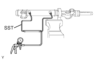 |
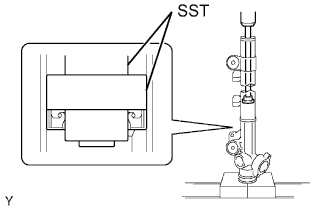
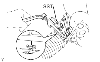
Install SST onto the rack housing.
Apply a vacuum of 53 kPa (400 mmHg, 15.75 in.Hg) for about 30 seconds.
Check that there is no change in the vacuum.
If there is any change in the vacuum, check whether the oil seals are installed correctly.
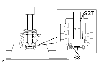
| 7. INSTALL POWER STEERING CONTROL VALVE UPPER OIL SEAL |
Coat the control valve upper bearing and a new control valve upper oil seal with power steering fluid.
Using SST and a press, install the control valve upper oil seal.
- SST
- 09950-60010
(09951-00180, 09951-00320, 09952-06010)
09950-70010 (09951-07150)
 |
Using SST and a press, install the control valve upper bearing.
- SST
- 09950-60010
(09951-00180, 09951-00340, 09952-06010)
09950-70010 (09951-07150)
 |
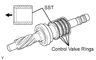
| 8. INSTALL POWER STEERING CONTROL VALVE ASSEMBLY |
|
Expand 4 new control valve rings with your fingers.
- NOTICE:
- Be careful not to over expand the control valve rings.
Coat the 4 control valve rings with power steering fluid.
Install the 4 control valve rings onto the control valve, and position them with your fingers.
Carefully slide the tapered end of SST over the control valve rings until they fit to the control valve.
- SST
- 09631-20081
- NOTICE:
- Be careful not to damage the control valve rings.
 |
To prevent the control valve upper oil seal lip from getting damaged, wind vinyl tape around the serrated portion of the control valve.
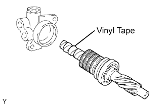 |
Coat the control valve upper oil seal lip with power steering fluid.
Install the control valve onto the control valve housing.
- NOTICE:
- Be careful not to damage the control valve ring and control valve upper oil seal lip.
Apply grease to the needle roller bearing.
Install a new O-ring onto the control valve housing.
Wind vinyl tape around the serrated portion of the control valve.
Install the control valve w/ control valve housing onto the rack housing with the 2 bolts.
- Torque:
- 21 N*m{ 214 kgf*cm , 14 ft.*lbf }
 |
| 9. INSTALL STEERING GEAR RACK GUIDE |
Install the rack guide.
Install the rack guide spring.
Apply adhesive to 2 or 3 threads of the rack guide spring cap.
- Adhesive:
- Toyota Genuine Adhesive 1344, Three Bond 1344 or equivalent
Provisionally install the rack guide spring cap.
| 10. ADJUST TOTAL PRELOAD |
To prevent the steering rack teeth from damaging the oil seal lip, provisionally install the RH and LH steering rack end.
Using 32 mm hexagon wrench, torque the rack guide spring cap.
- Torque:
- 30 N*m{ 306 kgf*cm , 22 ft.*lbf }
Using 32 mm hexagon wrench, loosen the rack guide spring cap.
 |
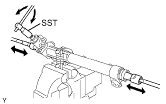
Using SST, turn the control valve to the right and left once or twice.
- SST
- 09616-00011
 |
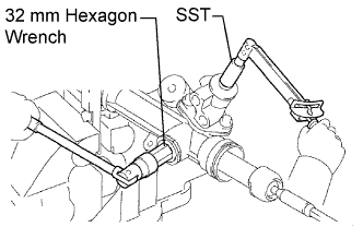
Using SST, loosen the rack guide spring cap until the rack guide spring ceases to function.
Using SST, a torque wrench and 32 mm hexagon wrench, tighten the cap until the preload is within the specification.
- SST
- 09616-00011
- Preload (turning):
- 1.9 to 2.7 N*m (19.4 to 27.5 kgf*cm, 16.8 to 23.9 in.*lbf)
 |
Apply adhesive to 2 or 3 threads of the rack guide spring cap nut.
- Adhesive:
- Toyota Genuine Adhesive 1344, Three Bond 1344 or equivalent
Provisionally install the rack guide spring cap nut.
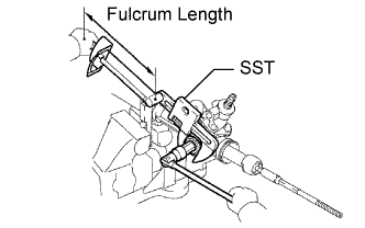
Using SST, hold the rack guide spring cap and using 32 mm hexagon wrench, torque the rack guide spring cap nut.
- SST
- 09922-10010
- Torque:
- without SST:
- 85 N*m{ 867 kgf*cm , 63 ft.*lbf }
- with SST:
- 62 N*m{ 632 kgf*cm , 46 ft.*lbf }
- NOTICE:
- Turn SST 09922-10010 in the direction shown in the illustration.
- HINT:
- Use a torque wrench with a fulcrum length of 345 mm (13.58 in.).
 |
Recheck the total preload.
- Preload (turning):
- 1.9 to 2.7 N*m (19.4 to 27.5 kgf*cm, 16.8 to 23.9 in.*lbf)
Remove the RH and LH steering rack ends.
Apply MP grease to the control valve as shown in the illustration.
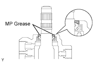 |
Wind vinyl tape around the serrated portion of the control valve.
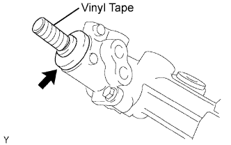 |
Install the dust cover onto the control valve housing.
| 11. INSTALL STEERING RACK END SUB-ASSEMBLY |
 |
Install 2 new claw washers, and provisionally install the 2 steering rack ends.
- HINT:
- Align the claws of the claw washers with the power steering rack grooves.
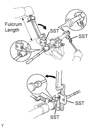
Using 2 SST, install the 2 steering rack ends.
- SST
- 09922-10010
- Torque:
- without SST:
- 195 N*m{ 1988 kgf*cm , 144 ft.*lbf }
- with SST:
- 142 N*m{ 1448 kgf*cm , 105 ft.*lbf }
- NOTICE:
- Turn SST 09922-10010 in the direction shown in the illustration.
- HINT:
- Using SST, hold the power steering rack and install the rack end sub-assembly.
- Use a torque wrench with a fulcrum length of 345 mm (13.6 in.).
Using a brass bar and hammer, stake the 2 claw washers.
- NOTICE:
- Avoid any impact to the power steering rack.
 |
| 12. INSPECT STEERING RACK END SUB-ASSEMBLY |
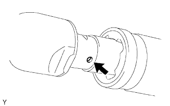 |
Ensure that the steering rack end hole is not clogged with grease.
- HINT:
- If the hole is clogged, the pressure inside the boot will change after it has been assembled, when the steering wheel is turned.
| 13. INSTALL STEERING RACK BOOT NO. 1 |
| 14. INSTALL STEERING RACK BOOT NO. 2 |
| 15. INSTALL STEERING RACK BOOT NO. 1 CLAMP |
 |
Using SST, tighten the rack boot No. 1 clamp as shown in the illustration.
- SST
- 09521-24010
- Clearance:
- 3.0 mm (0.118 in.) or less
- NOTICE:
- Be careful not to damage the rack boot No. 1.
| 16. INSTALL STEERING RACK BOOT NO. 2 CLAMP |
- HINT:
- The installation procedure for the No. 2 side is the same as that for the No. 1 side.
| 17. INSTALL STEERING RACK BOOT CLIP |
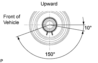 |
Using pliers, install the 2 rack boot clips.
- NOTICE:
- Make sure that each clip's claws are positioned within the area shown in the illustration.
| 18. INSTALL TIE ROD END SUB-ASSEMBLY LH |
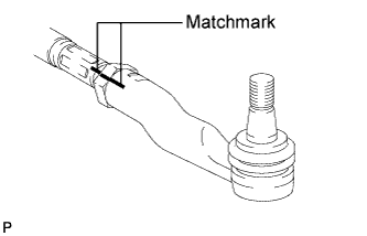 |
Align the matchmarks of the tie rod and rack end and temporarily install the tie rod with the lock nut.
After adjusting toe-in, torque the nut.
- Torque:
- 82 N*m{ 836 kgf*cm , 60 ft.*lbf }
| 19. INSTALL TIE ROD END SUB-ASSEMBLY RH |
- HINT:
- The installation procedure for the RH side is the same as that for the LH side.
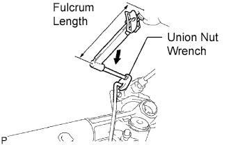
| 20. INSTALL STEERING TURN PRESSURE TUBE |
Coat 4 new O-rings with power steering fluid and install them onto the pressure tubes.
Using union nut wrench, install the 2 pressure tubes.
- Torque:
- 18 N*m{ 184 kgf*cm , 13 ft.*lbf }
- NOTICE:
- Use the formula calculate special torque values for situations for situations where a union nut wrench is combined with a torque wrench (Click here).
 |