TRANSFER ASSEMBLY > REASSEMBLY |

for Preparation Click here
| 1. INSTALL BREATHER OIL DEFLECTOR |
 |
Install a new deflector with the 2 bolts.
- Torque:
- 6.5 N*m{ 66 kgf*cm , 58 in.*lbf }
| 2. INSTALL RING GEAR MOUNTING CASE WASHER |
Install a new washer to the transfer case.
- HINT:
- Install a washer of the same thickness as the previous one.
| 3. INSTALL TRANSFER RING GEAR MOUNTING CASE NO. 2 WASHER |
Install a new washer to the cover.
- HINT:
- Install a washer of the same thickness as the previous one.
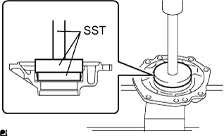
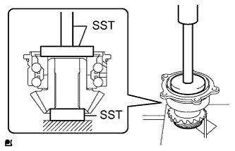
| 4. INSTALL TRANSFER RING GEAR MOUNTING CASE |
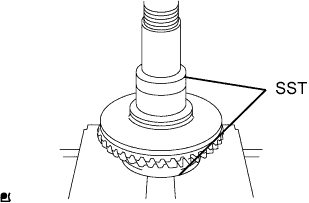 |
Using SST and a press, press in the mounting case to the ring gear.
- SST
- 09316-12010
09950-60010 (09951-00560)
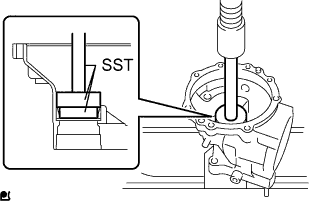
| 5. INSTALL SHAFT SNAP RING |
 |
Using a snap ring expander, install a new snap ring.
| 6. INSTALL RING GEAR MOUNTING CASE BEARING (for RH Side) |
Using SST and a press, press in the bearing (race) to the cover.
- SST
- 09950-60020
(09951-00750, 09952-06010)
09950-70010 (09951-07150)
 |
Using SST and a press, press in the bearing to the mounting case.
- SST
- 09336-16010
09950-60010 (09951-00400)
 |
Apply gear oil to the bearing.
| 7. INSTALL RING GEAR MOUNTING CASE BEARING (for LH Side) |
Using SST and a press, press in the bearing (race) to the case.
- SST
- 09950-60010
(09951-00540, 09951-00620, 09952-06010)
09950-70010 (09951-07150)
 |
Using SST and a press, press in the bearing to the mounting case.
- SST
- 09336-16010
09950-60010 (09951-00560)
 |
Apply gear oil to the mounting case bearing.
| 8. INSTALL TRANSFER OUTPUT SHAFT WASHER |
 |
Install the washer to the driven pinion.
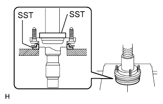
| 9. INSTALL TRANSFER DRIVEN PINION FRONT BEARING |
 |
Using SST and a press, press in the bearing to the driven pinion.
- SST
- 09950-60010
(09951-00440)
09950-60020 (09951-00750)
09950-70010 (09951-07150)
| 10. INSTALL TRANSFER OUTPUT REAR SHAFT DUST DEFLECTOR |
 |
Using SST and a press, press in the dust deflector to the output shaft.
- SST
- 09316-12010
09950-60020 (09951-00680)
| 11. INSTALL TRANSFER DRIVEN PINION |
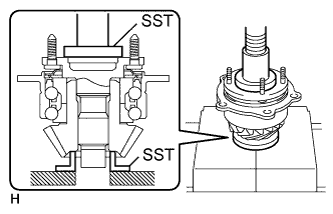 |
Using SST and a press, press in the driven pinion to the output rear shaft.
- SST
- 09506-30012
09950-60020 (09951-00680)
Install a new nut to the output shaft.
- Torque:
- 360 N*m{ 3700 kgf*cm , 266 ft.*lbf }
 |
| 12. INSTALL TRANSFER OUTPUT REAR SHAFT SUB-ASSEMBLY |
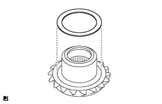
Install a new O-ring to the transfer driven pinion front bearing.
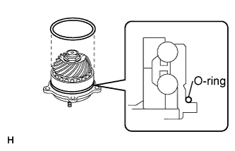 |
Install the transfer output rear shaft to the case with the 5 bolts.
- Torque:
- 38 N*m{ 390 kgf*cm , 28 ft.*lbf }
 |
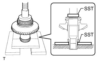
| 13. INSPECT TRANSFER DRIVEN PINION FRONT BEARING PRELOAD |
 |
Using a torque wrench, measure the preload.
- Standard preload (turning):
- 0.17 to 1.86 N*m (1.7 to 19.0 kgf*cm, 1.5 to 16.5 in.*lbf)
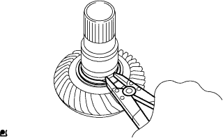
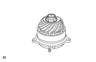
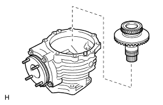
| 14. INSTALL TRANSFER RING GEAR |
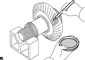 |
Coat 3 or 4 teeth in 4 different positions on the ring gear with Prussian blue.
Install the mounting case to the transfer case.
 |
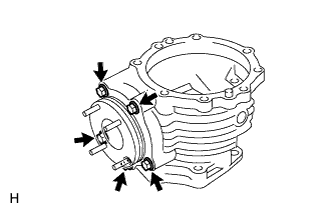
| 15. INSTALL NO. 1 TRANSFER CASE COVER |
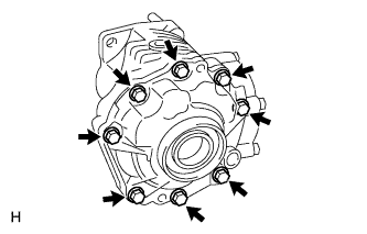 |
Install the No. 1 transfer case cover with the 8 bolts.
- Torque:
- 47 N*m{ 480 kgf*cm , 35 ft.*lbf }
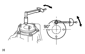
| 16. ADJUST RING GEAR BACKLASH |
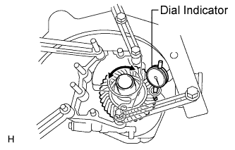 |
Using a dial indicator, measure the backlash of the ring gear at no fewer than 3 positions.
- Standard backlash:
- 0.10 to 0.20 mm (0.0039 to 0.0079 in.)
- HINT:
- The measurement values should be used as reference when selecting a washer, so take a note of the values. If the backlash is not within the specification, replace the washer on the ring gear side with one that has a different thickness using the following procedure.
- Standard washer thickness:
Mark Thickness Mark Thickness A0 1.97 mm (0.0776 in.) C0 2.37 mm (0.0933 in.) A1 1.99 mm (0.0783 in.) C1 2.39 mm (0.0941 in.) A2 2.01 mm (0.0791 in.) C2 2.41 mm (0.0949 in.) A3 2.03 mm (0.0799 in.) C3 2.43 mm (0.0957 in.) A4 2.05 mm (0.0807 in.) C4 2.45 mm (0.0965 in.) A5 2.07 mm (0.0815 in.) C5 2.47 mm (0.0972 in.) A6 2.09 mm (0.0823 in.) C6 2.49 mm (0.0980 in.) A7 2.11 mm (0.0831 in.) C7 2.51 mm (0.0988 in.) A8 2.13 mm (0.0839 in.) C8 2.53 mm (0.0996 in.) A9 2.15 mm (0.0846 in.) C9 2.55 mm (0.1004 in.) B0 2.17 mm (0.0854 in.) D0 2.57 mm (0.1012 in.) B1 2.19 mm (0.0862 in.) D1 2.59 mm (0.1019 in.) B2 2.21 mm (0.0870 in.) D2 2.61 mm (0.1028 in.) B3 2.23 mm (0.0878 in.) D3 2.63 mm (0.1035 in.) B4 2.25 mm (0.0886 in.) D4 2.65 mm (0.1043 in.) B5 2.27 mm (0.0894 in.) D5 2.67 mm (0.1051 in.) B6 2.29 mm (0.0902 in.) D6 2.69 mm (0.1059 in.) B7 2.31 mm (0.0909 in.) D7 2.71 mm (0.1067 in.) B8 2.33 mm (0.0917 in.) D8 2.73 mm (0.1075 in.) B9 2.35 mm (0.0925 in.) D9 2.75 mm (0.1083 in.)
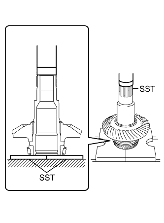
| 17. ADJUST TOTAL PRELOAD |
|
Using a torque wrench, measure the total preload.
- Standard driven pinion preload:
- 0.28 to 0.79 N*m (2.86 to 8.06 kgf*cm, 2.48 to 7.0 in.*lbf)
- HINT:
- Turn the driven pinion counterclockwise and clockwise several times.
- If the preload is not as standard, select a proper washer again.
- Standard washer thickness:
Mark Thickness Mark Thickness A0 1.18 mm (0.0465 in.) C2 1.62 mm (0.0638 in.) A1 1.20 mm (0.0472 in.) C3 1.64 mm (0.0646 in.) A2 1.22 mm (0.0480 in.) C4 1.66 mm (0.0654 in.) A3 1.24 mm (0.0488 in.) C5 1.68 mm (0.0661 in.) A4 1.26 mm (0.0496 in.) C6 1.70 mm (0.0669 in.) A5 1.28 mm (0.0504 in.) C7 1.72 mm (0.0677 in.) A6 1.30 mm (0.0512 in.) C8 1.74 mm (0.0685 in.) A7 1.32 mm (0.0519 in.) C9 1.76 mm (0.0693 in.) A8 1.34 mm (0.0528 in.) D0 1.78 mm (0.0701 in.) A9 1.36 mm (0.0535 in.) D1 1.80 mm (0.0709 in.) B0 1.38 mm (0.0543 in.) D2 1.82 mm (0.0717 in.) B1 1.40 mm (0.0551 in.) D3 1.84 mm (0.0724 in.) B2 1.42 mm (0.0559 in.) D4 1.86 mm (0.0732 in.) B3 1.44 mm (0.0567 in.) D5 1.88 mm (0.0740 in.) B4 1.46 mm (0.0575 in.) D6 1.90 mm (0.0748 in.) B5 1.48 mm (0.0583 in.) D7 1.92 mm (0.0756 in.) B6 1.50 mm (0.0591 in.) D8 1.94 mm (0.0764 in.) B7 1.52 mm (0.0598 in.) D9 1.96 mm (0.0772 in.) B8 1.54 mm (0.0606 in.) E0 1.98 mm (0.0780 in.) B9 1.56 mm (0.0614 in.) E1 2.00 mm (0.0787 in.) C0 1.58 mm (0.0622 in.) E2 2.02 mm (0.0795 in.) C1 1.60 mm (0.0629 in.) - -
| 18. INSPECT TOOTH CONTACT BETWEEN RING GEAR AND DRIVE PINION |
Rotate the ring gear several times.
Look through the service filler hole or remove the ring gear to check the tooth contact pattern.
- NOTICE:
- Check the tooth contact pattern at 4 or more positions around the circumference of the ring gear.
- When replacing washers (backlash adjustment, preload adjustment or tooth contact adjustment), reapply Prussian blue.
- HINT:
- The Prussian blue pattern indicates the tooth contact points.
If the teeth are not contacting properly, select a driven pinion bearing front (outer race) side washer from the chart and install the washer.
- NOTICE:
- If a washer (for tooth contact adjustment) is replaced with one that has a different thickness, the backlash will also change. Therefore, it is necessary to adjust the backlash.
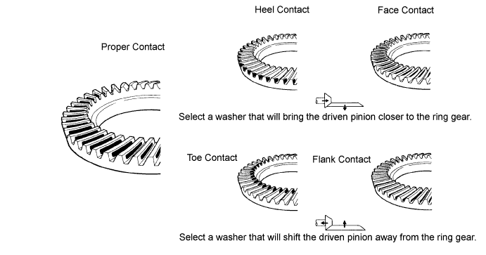
Perform the following procedures for face or flank contact:
Use the backlash adjustment washer (ring gear mounting case washer) to move and adjust the ring gear. (*1)
Perform the ring gear and driven pinion tooth contact inspection again.
- HINT:
- If the tooth contact is incorrect, repeat step *1.
Perform the ring gear and driven pinion backlash inspection. If the ring gear and driven pinion backlash is not within the standard range, replace the ring gear and driven pinion with new ones.
Perform the following procedures for heel or toe contact:
Select a transfer driven pinion bearing front (outer race) side washer (transfer output shaft washer) from the chart and install the washer.
- NOTICE:
- Do not reuse a transfer pinion bearing spacer.
- Standard washer thickness:
Mark Thickness Mark Thickness 01 1.02 mm (0.0402 in.) 15 1.30 mm (0.0512 in.) 02 1.04 mm (0.0409 in.) 16 1.32 mm (0.0520 in.) 03 1.06 mm (0.0417 in.) 17 1.34 mm (0.0528 in.) 04 1.08 mm (0.0425 in.) 18 1.36 mm (0.0535 in.) 05 1.10 mm (0.0433 in.) 19 1.38 mm (0.0543 in.) 06 1.12 mm (0.0441 in.) 20 1.40 mm (0.0551 in.) 07 1.14 mm (0.0449 in.) 21 1.42 mm (0.0559 in.) 08 1.16 mm (0.0457 in.) 22 1.44 mm (0.0567 in.) 09 1.18 mm (0.0465 in.) 23 1.46 mm (0.0575 in.) 10 1.20 mm (0.0472 in.) 24 1.48 mm (0.0583 in.) 11 1.22 mm (0.0480 in.) 25 1.50 mm (0.0591 in.) 12 1.24 mm (0.0488 in.) 26 1.52 mm (0.0598 in.) 13 1.26 mm (0.0496 in.) 27 1.54 mm (0.0606 in.) 14 1.28 mm (0.0504 in.) 28 1.56 mm (0.0614 in.)
| 19. COMPLETELY INSTALL TRANSFER OUTPUT REAR SHAFT SUB-ASSEMBLY |
Using a chisel and a hammer, stake the pinion gear nut.
Install the transfer output rear shaft to the case with the 5 bolts.
- Torque:
- 38 N*m{ 390 kgf*cm , 28 ft.*lbf }
|
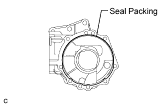
Install the No. 1 transfer case cover.
Using a non-residue solvent, clean the contact surfaces of the housing and cover.
Apply seal packing to the cover as shown in the illustration.
- Seal Packing:
- Toyota Genuine Seal Packing 1281, Three Bond 1281 or equivalent
Install the cover to the case with the 8 bolts.
- Torque:
- 47 N*m{ 480 kgf*cm , 35 ft.*lbf }
| 20. INSTALL TRANSFER CASE OIL SEAL LH |
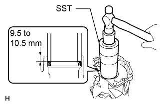 |
Using SST and a hammer, tap in the transfer case oil seal.
- SST
- 09316-60011
(09316-00011)
- Standard depth:
- 9.5 to 10.5 mm (0.37 to 0.41 in.)
- NOTICE:
- Do not damage the oil seal lip.
Coat a new oil seal lip with MP grease.
| 21. INSTALL TRANSFER CASE OIL SEAL RH |
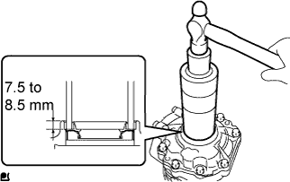 |
Using SST and a hammer, tap in the oil seal.
- SST
- 09316-60011
(09316-00011)
- Standard depth:
- 7.5 to 8.5 mm (0.30 to 0.33 in.)
- NOTICE:
- Do not damage the oil seal lip.
Coat a new oil seal lip with MP grease.
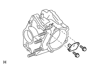
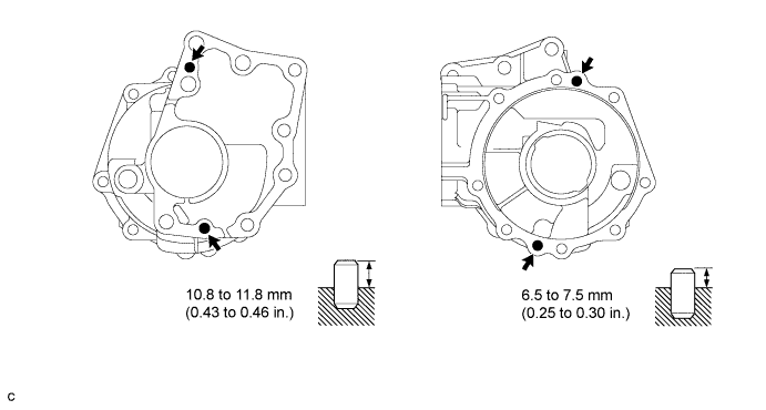
| 22. INSTALL TRANSFER CASE STRAIGHT PIN |
Using a plastic-faced hammer, install the straight pins as shown in the illustration.
| 23. INSTALL TRANSFER CASE BREATHER PLUG |
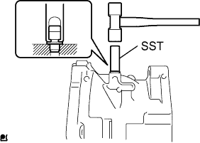 |
Using SST and a hammer, tap in a new breather plug.
- SST
- 09612-10093
(09612-10061)
| 24. INSTALL TRANSFER DRAIN PLUG |
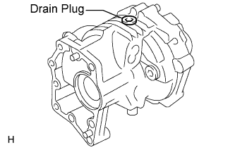 |
Install a new gasket and the plug to the transfer case.
- Torque:
- 39 N*m{ 398 kgf*cm , 29 ft.*lbf }
| 25. INSTALL TRANSFER CASE NO. 1 PLUG |
Install a new gasket and the plug to the transfer case.
- Torque:
- 39 N*m{ 398 kgf*cm , 29 ft.*lbf }
| 26. INSTALL TRANSFER CASE NO. 2 PLUG |
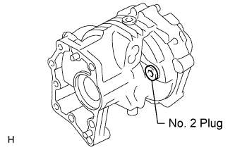 |
Install a new gasket and the plug to the transfer case.
- Torque:
- 39 N*m{ 398 kgf*cm , 29 ft.*lbf }
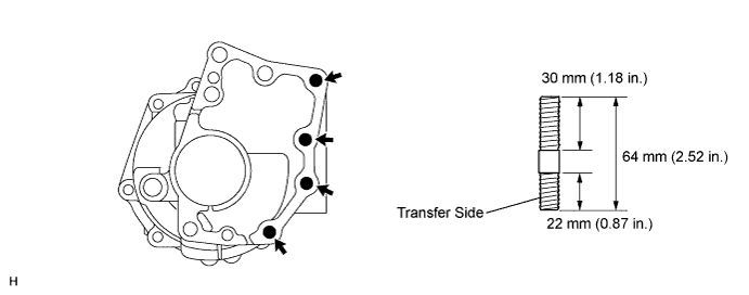
| 27. INSTALL TRANSFER AND TRANSAXLE SETTING STUD BOLT |
Apply sealer to the stud bolts.
Install the stud bolts.
- Torque:
- 39 N*m{ 398 kgf*cm , 29 ft.*lbf }
- HINT:
- Install the transfer side of each stud bolt (see the illustration below) to the case.