LOWER INSTRUMENT PANEL > INSTALLATION |

for Preparation Click here
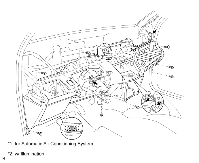
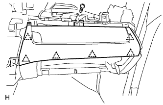
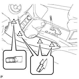
| 1. INSTALL LOWER INSTRUMENT PANEL |
Connect the connectors, attach the clamps and install the lower instrument panel.
w/ Illumination:
Connect the connectors.
for Automatic Air Conditioning System:
Install the cooler thermistor hose and connect the connector.
Attach the claws to install the DLC3.
Install the 4 bolts, 2 screws and 2 clips.
| 2. INSTALL NO. 6 HEATER TO REGISTER DUCT ASSEMBLY (w/ Cool Box) |
Attach the 2 claws to install the duct.
 |
Install the 2 screws.
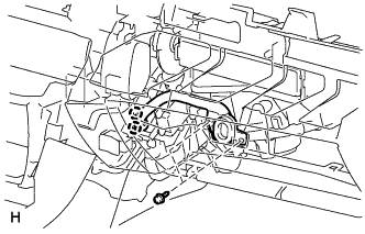
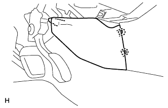
| 3. INSTALL HOOD LOCK CONTROL LEVER SUB-ASSEMBLY |
Attach the 3 claws to install the hood lock control lever.
 |
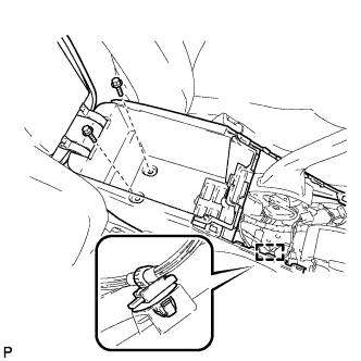
| 4. INSTALL POWER STEERING ECU ASSEMBLY |
Install the ECU with the 3 nuts.
- Torque:
- 8.5 N*m{ 87 kgf*cm , 75 in.*lbf }
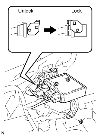 |
Connect the connectors.
- NOTICE:
- Be sure to engage the lock of the connector as shown in the illustration.
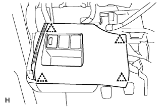
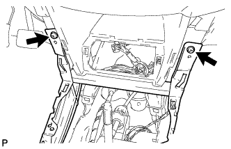
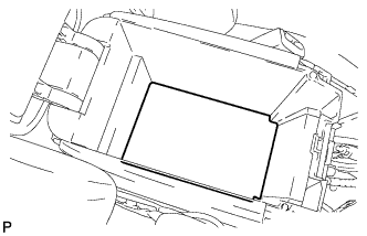
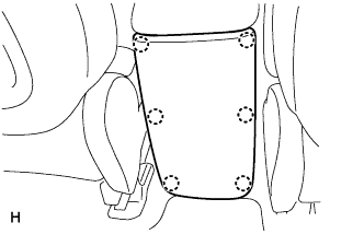
| 5. INSTALL INSTRUMENT PANEL BOX |
Attach the 6 clips to install the instrument panel box.
 |
Install the screw.
| 6. INSTALL NO. 1 SWITCH HOLE BASE |
Connect the connectors.
 |
Attach the 4 clips to install the switch hole base.
| 7. INSTALL COWL SIDE TRIM BOARD RH |
- HINT:
- Use the same procedure described for the LH side.
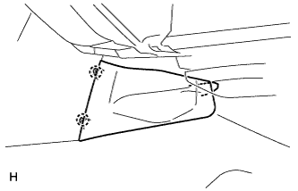
| 8. INSTALL COWL SIDE TRIM BOARD LH |
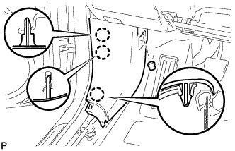 |
Attach the 3 claws to install the trim board.
Install the cap nut.
| 9. INSTALL FRONT DOOR SCUFF PLATE RH |
- HINT:
- Use the same procedure described for the LH side.
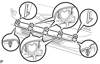
| 10. INSTALL FRONT DOOR SCUFF PLATE LH |
Attach the 10 claws to install the scuff plate.
 |
| 11. INSTALL NO. 2 INSTRUMENT PANEL UNDER COVER SUB-ASSEMBLY |
 |
Attach the 3 claws to install the instrument panel under cover.
| 12. INSTALL LOWER INSTRUMENT PANEL FINISH PANEL (w/o Driver Side Knee Airbag) |
 |
Attach the 8 claws to install the lower instrument panel finish panel.
Install the 2 screws.
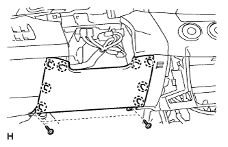
| 13. INSTALL DRIVER SIDE KNEE AIRBAG ASSEMBLY (w/ Driver Side Knee Airbag) |
 |
Connect the connector.
- NOTICE:
- When handling the airbag connector, take care not to damage the airbag wire harness.
Install the driver side knee airbag with the 4 bolts.
- Torque:
- 10 N*m{ 101 kgf*cm , 7 ft.*lbf }
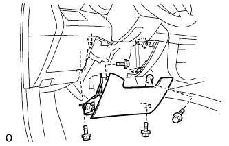
| 14. INSTALL NO. 1 INSTRUMENT PANEL UNDER COVER SUB-ASSEMBLY (w/ Driver Side Knee Airbag) |
Attach 3 claws to install the instrument panel under cover.
 |
Install the 2 screws.
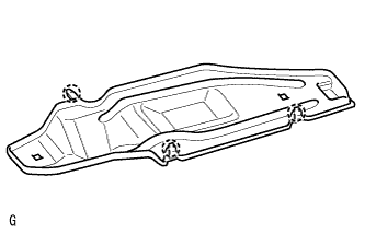
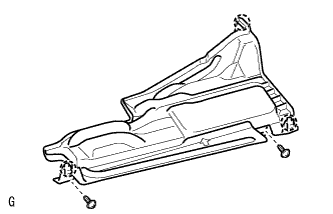
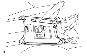
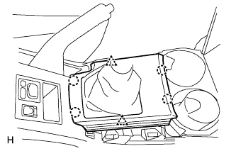
| 15. INSTALL REAR CONSOLE BOX SUB-ASSEMBLY |
Connect the connector.
Install the rear console box with the 2 bolts and attach the wire harness clamp.
 |
Install the 2 screws.
 |
| 16. INSTALL CONSOLE BOX CARPET |
Install the console box carpet.
 |
| 17. INSTALL NO. 1 INSTRUMENT PANEL BRACKET COVER INNER LH |
Attach the 2 claws to install the instrument panel bracket cover.
 |
| 18. INSTALL NO. 1 INSTRUMENT PANEL BRACKET COVER INNER RH |
Attach the 2 claws to install the instrument panel bracket cover.
 |
| 19. INSTALL CONSOLE REAR END PANEL |
Attach the 6 claws to install the console rear end panel.
 |
| 20. INSTALL UPPER REAR CONSOLE PANEL SUB-ASSEMBLY |
Connect the connector.
 |
Attach the 4 clips to install the upper rear console panel.
| 21. INSTALL CONSOLE CUP HOLDER BOX |
Attach the 2 clips to install the cup holder box.
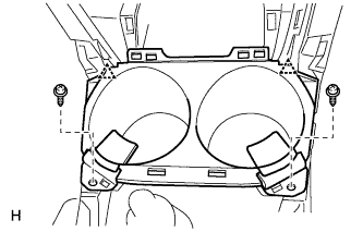 |
Install the 2 screws.
| 22. INSTALL SWITCH BASE |
Connect the connectors.
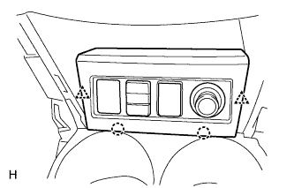 |
Attach the 2 clips and 2 claws to install the switch base.
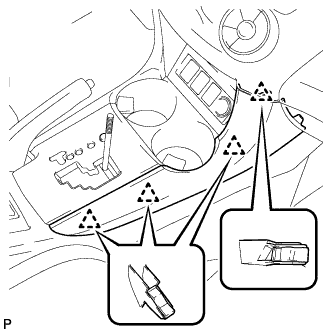
| 23. INSTALL UPPER CONSOLE PANEL SUB-ASSEMBLY (for Manual Transaxle) |
Attach the 2 clips and 4 claws to install the upper console panel.
 |
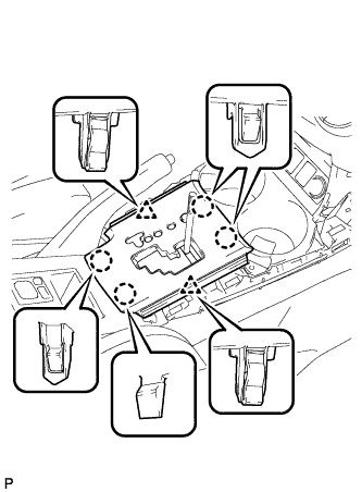
| 24. INSTALL FLOOR SHIFT POSITION INDICATOR HOUSING SUB-ASSEMBLY (for Automatic Transaxle) |
Connect the connector.
Attach the 2 clips and 4 claws to install the floor shift position indicator housing.
 |
| 25. INSTALL NO. 2 CONSOLE UPPER PANEL GARNISH |
Attach the 4 clips to install the upper panel garnish.
 |
| 26. INSTALL NO. 1 CONSOLE UPPER PANEL GARNISH |
Attach the 4 clips to install the upper panel garnish.
 |
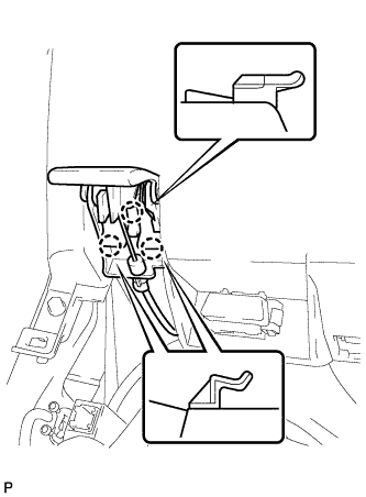
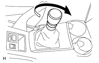
| 27. INSTALL SHIFT LEVER KNOB SUB-ASSEMBLY |
for Manual Transaxle:
Twist the shift lever knob in the direction indicated by the arrow to install it.
 |
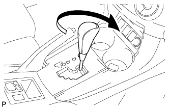
for Automatic Transaxle:
Twist the shift lever knob in the direction indicated by the arrow to install it.
 |
| 28. INSTALL HEATER CONTROL SUB-ASSEMBLY (for Automatic Air Conditioning System) |
Connect the connectors.
 |
Attach the 3 clips to install the air conditioning control.
Install the 2 screws.
| 29. INSTALL HEATER CONTROL SUB-ASSEMBLY (for Manual Air Conditioning System) |
Connect the connectors.
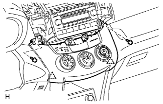 |
Attach the 3 clips to install the air conditioning control.
Install the 2 screws.
| 30. INSTALL COMBINATION SWITCH ASSEMBLY |
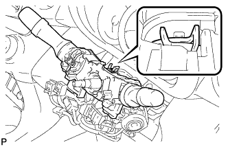 |
Install the turn signal switch onto the steering column with the clamp.
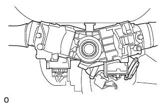
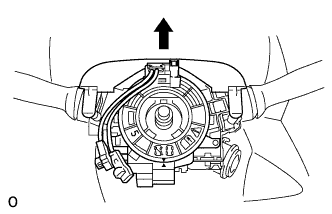
| 31. INSTALL SPIRAL CABLE SUB-ASSEMBLY |
Check that the front wheels are facing straight ahead.
Set the turn signal switch to the neutral position.
- NOTICE:
- Make sure that the turn signal switch is in the neutral position, as the pin of the turn signal switch may be snapped.
Install the spiral cable.
- NOTICE:
- When replacing the spiral cable with a new one, remove the lock pin before installing the steering wheel.
 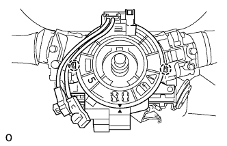 |
Connect the connectors to the spiral cable.
- NOTICE:
- When handling the airbag connector, do not damage the airbag wire harness.
Attach the 4 clips to the column cover (upper).
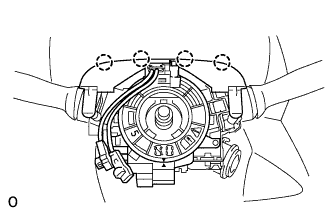 |
Install the steering column cover (upper).
 |
| 32. INSTALL STEERING COLUMN COVER |
for LHD:
Install the steering column cover (Click here).
for RHD:
Install the steering column cover (Click here).
| 33. INSTALL INSTRUMENT PANEL SUB-ASSEMBLY |
Install the instrument panel (Click here).
| 34. CONNECT CABLE TO NEGATIVE BATTERY TERMINAL |
| 35. CHECK SRS WARNING LIGHT |
Check the SRS warning light (Click here).