ECD SYSTEM (for CCo) > DATA LIST / ACTIVE TEST |

for Preparation Click here
| DATA LIST |
- HINT:
- Using the intelligent tester to read the Data List allows the values or states of switches, sensors, actuators and other items to be read without removing any parts. This non-intrusive inspection can be very useful because intermittent conditions or signals may be discovered before parts or wiring is disturbed. Reading the Data List information early in troubleshooting is one way to save diagnostic time.
- NOTICE:
- In the table below, the values listed under "Normal Condition" are reference values. Do not depend solely on these reference values when deciding whether a part is faulty or not.
Warm up the engine.
Turn the ignition switch off.
Connect the intelligent tester to the DLC3.
Turn the ignition switch to ON.
Start the engine.
Turn the intelligent tester on.
Enter the following menus: Powertrain / Engine and ECT / Data List.
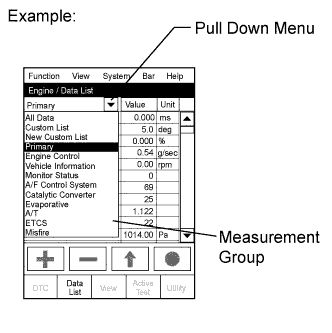
- HINT:
- To display the list box, press the pull down menu button next to Primary. Then select a measurement group.
- When you select a measurement group, the ECU data belonging to that group is displayed.
- Measurement Group List / Description
- All Data / All data
- Primary / -
- Engine Control / Engine control system related data
- Vehicle Information / Vehicle information
- Monitor Status / Monitor status related data
- AF Control System / Not Applicable
- Catalytic Converter / Not Applicable
- Evaporative / Not Applicable
- A/T / Automatic transmission system related data
- ETCS / Not Applicable
- Misfire / Not Applicable
- Compression / Data used during "Check the Cylinder Compression" in "Active Test"
- HC Adsorber System / Not Applicable
- Diesel Driving / Driving condition data
- Diesel Injection / Fuel system related data
- Diesel EGR / EGR system related data
- Diesel Throttle / Diesel throttle system related data
- Diesel VN Turbo / VN turbo related data
- Diesel Exhaust / Exhaust system related data
- Diesel Starting / "Difficult to start" related data
- Diesel Rough / "Rough idle" related data
- Diesel Power / "Lack of power" related data
Check the values by referring to the table below.
- HINT:
- "Result of real-vehicle check" is the assessment of one vehicle. Use it only for reference.
 |
| Engine Control |
| Tester Display | Measurement Item/Range | Normal Condition | Type | Cause of Out of Range |
| Calculate Load | Calculated load by ECM/ Min.: 0%, Max.: 100% |
| Calculated by ECM | Malfunction in which turbo pressure or Mass Air Flow (MAF) decreases |
Results of real-vehicle check:
| ||||
| Diagnostic Note: Calculated load = (Final injection volume / max. injection volume at current engine speed) x 100. | ||||
| Tester Display | Measurement Item/Range | Normal Condition | Type | Cause of Out of Range |
| MAF | Air flow rate from MAF meter/ Min.: 0 g/sec., Max.: 400 g/sec. |
| Sensor output (MAF meter) |
|
Results of real-vehicle check:
| ||||
| Symptoms when out of range: Rough idling | ||||
Diagnostic Note:
| ||||
| Tester Display | Measurement Item/Range | Normal Condition | Type | Cause of Out of Range |
| Engine Speed | Engine speed/ Min.: 0 rpm, Max.: 6000 rpm |
| Sensor output (crankshaft position sensor) |
|
| Symptoms when out of range: - | ||||
| Diagnostic Note: When the crankshaft position sensor is malfunctioning, "Engine speed" is approximately 0 or varies greatly from the actual engine speed. | ||||
| Tester Display | Measurement Item/Range | Normal Condition | Type | Cause of Out of Range |
| MAP | Absolute pressure inside intake manifold/ Min.: 0 kPa, Max.: 255 kPa |
| Sensor output (manifold absolute pressure sensor) |
|
Results of real-vehicle check:
| ||||
| Symptoms when out of range: Lack of power | ||||
Diagnostic Note:
| ||||
| Tester Display | Measurement Item/Range | Normal Condition | Type | Cause of Out of Range |
| Vehicle Speed | Vehicle speed/ Min.: 0 km/h, Max.: 255 km/h | Actual vehicle speed | Sensor output (speed sensor) |
|
| Symptoms when out of range: - | ||||
| Diagnostic Note: - | ||||
| Tester Display | Measurement Item/Range | Normal Condition | Type | Cause of Out of Range |
| Coolant Temp | Engine coolant temperature/ Min.: -40°C, Max.: 140°C | After warming up engine: 60 to 90°C (140 to 194°F) | Sensor output (engine coolant temperature sensor) |
|
| Symptoms when out of range: Difficult starting when engine is cold, rough idle, black smoke, lack of power | ||||
Diagnostic Note:
| ||||
| Tester Display | Measurement Item/Range | Normal Condition | Type | Cause of Out of Range |
| Intake Air | Intake air temperature/ Min.: -40°C, Max.: 140°C | Equivalent to temperature at intake manifold | Sensor output (intake air temperature sensor (built into MAF meter)) | Intake air temperature sensor |
| Symptoms when out of range: - | ||||
Diagnostic Note:
| ||||
| Tester Display | Measurement Item/Range | Normal Condition | Type | Cause of Out of Range |
| Initial Engine Coolant Temp | Initial engine coolant temperature/ Min.: -40°C, Max.: 120°C | Engine coolant temperature when engine started | Sensor output when engine started | - |
| Diagnostic Note: For Freeze Frame Data, this tells whether the malfunction happened at a cold start or with a warm engine. | ||||
| Tester Display | Measurement Item/Range | Normal Condition | Type | Cause of Out of Range |
| Initial Intake Air Temp | Initial intake air temperature/ Min.: -40°C, Max.: 120°C | Intake air temperature when engine started | Sensor output when engine started | - |
| Diagnostic Note: - | ||||
| Tester Display | Measurement Item/Range | Normal Condition | Type | Cause of Out of Range |
| Intake Air Temp (Turbo) | Intake air temperature after intercooler/ Min.: -40°C, Max.: 190°C | 70°C (158°F) or less | Sensor output (intake air temperature sensor after intercooler) | Decreased cooling efficiency of intercooler (contamination, clogging) |
Diagnostic Note:
| ||||
| Tester Display | Measurement Item/Range | Normal Condition | Type | Cause of Out of Range |
| Pre Glow | Pre-glow operation/ ON or OFF | - | Result of ECU calculations | - |
| Diagnostic Note: This is the ECM command. | ||||
| Tester Display | Measurement Item/Range | Normal Condition | Type | Cause of Out of Range |
| After Glow | After-glow operation/ ON or OFF | - | Result of ECU calculations | - |
| Diagnostic Note: This is the ECM command. | ||||
| Tester Display | Measurement Item/Range | Normal Condition | Type | Cause of Out of Range |
| Alternate Duty Ratio | Alternator generation duty ratio/ Min.: 0%, Max.: 100% |
| Duty value from ALT terminal |
|
| Results of real-vehicle check: Idling (no electrical load) (warm up the engine): 41% (2 minutes after starting the vehicle) | ||||
| Symptoms when out of range: - | ||||
Diagnostic Note:
| ||||
| Tester Display | Measurement Item/Range | Normal Condition | Type | Cause of Out of Range |
| Starter Signal | Starter signal/ ON or OFF | ON: Cranking | - |
|
Symptoms when out of range:
| ||||
| Diagnostic Note: Ignition switch (STA) output:
| ||||
| Tester Display | Measurement Item/Range | Normal Condition | Type | Cause of Out of Range |
| A/C Signal | A/C (Air Conditioner) signal/ ON or OFF | ON: A/C on | A/C operation signal output from A/C amplifier
|
|
| Symptoms when out of range: OFF malfunction (OFF even when A/C switch is turned on):
| ||||
| Diagnostic Note: - | ||||
| Tester Display | Measurement Item/Range | Normal Condition | Type | Cause of Out of Range |
| Stop Light Switch | Stop light switch/ ON or OFF |
| Switch output (stop light switch) |
|
| Symptoms when out of range: Stop light switch malfunction DTC P0504 is stored | ||||
| Diagnostic Note: Stop light switch (STP) operation condition:
| ||||
| Tester Display | Measurement Item/Range | Normal Condition | Type | Cause of Out of Range |
| Immobiliser Communication | Immobiliser communication/ ON or OFF |
| - |
|
| Symptoms when out of range: - | ||||
| Diagnostic Note: - | ||||
| Tester Display | Measurement Item/Range | Normal Condition | Type | Cause of Out of Range |
| Clutch Switch | Clutch switch/ ON or OFF | ON: Clutch pedal depressed | Switch output (clutch switch) | - |
| Symptoms when out of range: When OFF with the clutch pedal depressed, the engine does not start. | ||||
| Diagnostic Note: - | ||||
| Tester Display | Measurement Item/Range | Normal Condition | Type | Cause of Out of Range |
| Battery Voltage | Battery voltage/ Min.: 0 V, Max.: 15 V | 11 to 14 V | - | - |
Results of real-vehicle check:
| ||||
| Symptoms when out of range: If 5 V or less, starting becomes difficult | ||||
| Diagnostic Note: If 11 V or less, characteristics of some electrical components change. | ||||
| Tester Display | Measurement Item/Range | Normal Condition | Type | Cause of Out of Range |
| Atmosphere Pressure | Atmospheric pressure value/ Min.: 50 kPa, Max.: 120 kPa | Actual atmospheric pressure | Sensor output (atmospheric pressure sensor (built into ECM)) | Atmospheric pressure sensor itself has failed (atmospheric pressure sensor is inside the ECM) |
| Symptoms when out of range: - | ||||
Diagnostic Note:
| ||||
| Tester Display | Measurement Item/Range | Normal Condition | Type | Cause of Out of Range |
| TC and TE1 | Connect the TC and TE1 status for Active Test/ ON or OFF | - | - | - |
| Diagnostic Note: When the Active Test "Connect the TC and TE1" is performed, the system behaves as if TC and CG were connected. | ||||
| Tester Display | Measurement Item/Range | Normal Condition | Type | Cause of Out of Range |
| # Codes (Include History) | Number of codes/ Min.: 0, Max.: 255 | - | - | - |
| Diagnostic Note: Number of DTCs appearing at least once during the last 40 times the vehicle was warmed up. | ||||
| Tester Display | Measurement Item/Range | Normal Condition | Type | Cause of Out of Range |
| Check Mode | Check mode/ ON or OFF | ON: Check mode on | - | - |
| Diagnostic Note: Check Mode: The mode in which certain DTCs can be detected more easily and with higher sensitivity. | ||||
| Tester Display | Measurement Item/Range | Normal Condition | Type | Cause of Out of Range |
| SPD Test Result | Check mode result for vehicle speed sensor/ Compl or Incompl | - | - | - |
| Diagnostic Note: SPD Test: Check mode result for vehicle speed sensor. | ||||
| Tester Display | Measurement Item/Range | Normal Condition | Type | Cause of Out of Range |
| MIL | MIL status/ ON or OFF | OFF: MIL off | - | - |
| Tester Display | Measurement Item/Range | Normal Condition | Type | Cause of Out of Range |
| MIL ON Run Distance | MIL on run distance/ Min.: 0 km, Max.: 65535 km | Distance after DTC stored | Result of ECU calculations (using the vehicle speed) | - |
Diagnostic Note:
| ||||
| Tester Display | Measurement Item/Range | Normal Condition | Type | Cause of Out of Range |
| Running Time from MIL ON | Running time from MIL on/ Min.: 0 min., Max.: 65535 min. | Running time after MIL turns on | - | - |
Diagnostic Note:
| ||||
| Tester Display | Measurement Item/Range | Normal Condition | Type | Cause of Out of Range |
| Engine Run Time | Engine run time/ Min.: 0 sec., Max.: 65535 sec. | Time after the ignition switch turned to ON | ECU calculations (using the engine speed) | - |
| Diagnostic Note: Time passed since the ignition switch was turned to ON. | ||||
| Tester Display | Measurement Item/Range | Normal Condition | Type | Cause of Out of Range |
| Time after DTC Cleared | Time after DTC cleared/ Min.: 0 min., Max.: 65535 min. | Time after DTCs cleared | - | - |
| Diagnostic Note: Time elapsed since the DTCs were cleared (or shipment from the factory). | ||||
| Tester Display | Measurement Item/Range | Normal Condition | Type | Cause of Out of Range |
| Distance from DTC Cleared | Distance after DTC cleared/ Min.: 0 km, Max.: 65535 km | Driving distance after DTCs were cleared | - | - |
Diagnostic Note:
| ||||
| Tester Display | Measurement Item/Range | Normal Condition | Type | Cause of Out of Range |
| Warmup Cycle Cleared DTC | Warmup cycle after DTC cleared/ Min.: 0, Max.: 255 | - | - | - |
Diagnostic Note:
| ||||
| Tester Display | Measurement Item/Range | Normal Condition | Type | Cause of Out of Range |
| OBD Requirements | Identifying OBD requirement | - | - | - |
| Diagnostic Note: Euro-OBD | ||||
| Tester Display | Measurement Item/Range | Normal Condition | Type | Cause of Out of Range |
| Number of Emission DTC | Number of emission DTCs | - | - | |
| Diagnostic Note: - | ||||
| Tester Display | Measurement Item/Range | Normal Condition | Type | Cause of Out of Range |
| Complete Parts Monitor | Complete parts monitor/ Not Avl or Avail | - | - | - |
| Diagnostic Note: - | ||||
| Tester Display | Measurement Item/Range | Normal Condition | Type | Cause of Out of Range |
| Engine Start Time | Engine start time/ Min.: 0 ms, Max.: 267000 ms | - | - | - |
| Diagnostic Note: Time necessary for the engine to start. | ||||
| Tester Display | Measurement Item/Range | Normal Condition | Type | Cause of Out of Range |
| Accel Position | Accelerator position status/ Min.: 0%, Max.: 100% |
|
| - |
Results of real-vehicle check:
| ||||
| Symptoms when out of range: - | ||||
Diagnostic Note:
| ||||
- HINT:
- Accel Sens. No.1 Volt % and Accel Sens. No.2 Volt % express the value obtained by dividing the output voltage from the accelerator pedal position sensor by 5. This is used only for diagnosing malfunctions in the accelerator pedal position sensor. Under normal conditions, it is sufficient to only check the accelerator opening angle final value "Accel Position".
| Tester Display | Measurement Item/Range | Normal Condition | Type | Cause of Out of Range |
| Accel Sens. No.1 Volt % | Accelerator position No. 1/ Min.: 0%, Max.: 100% |
| Sensor output (Accelerator pedal position sensor) | - |
| Diagnostic Note: Read value with ignition switch ON (do not start engine) | ||||
| Tester Display | Measurement Item/Range | Normal Condition | Type | Cause of Out of Range |
| Accel Sens. No.2 Volt % | Accelerator position No. 2/ Min.: 0%, Max.: 100% |
| Sensor output (Accelerator pedal position sensor) | - |
| Diagnostic Note: Read value with ignition switch ON (do not start engine) | ||||
| Compression |
| Tester Display | Measurement Item/Range | Normal Condition | Type | Cause of Out of Range |
| Engine Speed of Cyl #1 | Engine speed for No. 1 cylinder/ Min.: 0 rpm, Max.: 6000 rpm | "Engine speed" of all cylinders almost same | - | Cyl #1 compression goes down |
| Symptoms when out of range: When the engine speed of all cylinders is not equal, idling will be rough. | ||||
Diagnostic Note:
| ||||
| Tester Display | Measurement Item/Range | Normal Condition | Type | Cause of Out of Range |
| Engine Speed of Cyl #2 | Engine speed for No. 2 cylinder/ Min.: 0 rpm, Max.: 6000 rpm | - | - | - |
| Tester Display | Measurement Item/Range | Normal Condition | Type | Cause of Out of Range |
| Engine Speed of Cyl #3 | Engine speed for No. 3 cylinder/ Min.: 0 rpm, Max.: 6000 rpm | - | - | - |
| Tester Display | Measurement Item/Range | Normal Condition | Type | Cause of Out of Range |
| Engine Speed of Cyl #4 | Engine speed for No. 4 cylinder/ Min.: 0 rpm, Max.: 6000 rpm | - | - | - |
| Tester Display | Measurement Item/Range | Normal Condition | Type | Cause of Out of Range |
| Av Engine Speed of All Cyl | Engine speed for all cylinders/ Min.: 0 rpm, Max.: 6000 rpm | - | - | - |
Diagnostic Note:
| ||||
| Vehicle Information |
| Tester Display | Measurement Item/Range | Normal Condition | Type | Cause of Out of Range |
| Model Code | Model code | - | - | - |
| Diagnostic Note: Identifying model code: | ||||
| Tester Display | Measurement Item/Range | Normal Condition | Type | Cause of Out of Range |
| Engine Type | Engine type | - | - | - |
| Diagnostic Note: Identifying engine type: 2ADFTV | ||||
| Tester Display | Measurement Item/Range | Normal Condition | Type | Cause of Out of Range |
| Cylinder Number | Cylinder number/ Min.: 0, Max.: 255 | - | - | - |
| Diagnostic Note: Identifying cylinder number: 4 | ||||
| Tester Display | Measurement Item/Range | Normal Condition | Type | Cause of Out of Range |
| Transmission Type | Transmission type/ MT or ECT 6th | - | - | - |
| Diagnostic Note: Identifying transmission type:
| ||||
| Tester Display | Measurement Item/Range | Normal Condition | Type | Cause of Out of Range |
| Destination | Destination | - | - | - |
| Diagnostic Note: Identifying destination: | ||||
| Tester Display | Measurement Item/Range | Normal Condition | Type | Cause of Out of Range |
| Model Year | Model year/ Min.: 1900, Max.: 2155 | - | - | - |
| Diagnostic Note: Identifying model year: 200# | ||||
| Tester Display | Measurement Item/Range | Normal Condition | Type | Cause of Out of Range |
| System Identification | System identification | - | - | - |
| Diagnostic Note: Identifying engine type: Diesel | ||||
| Tester Display | Measurement Item/Range | Normal Condition | Type | Cause of Out of Range |
| VN Turbo Type | VN turbo type/ Not, Commo or Vacuum | Vacuum | - | - |
| Symptoms when out of range: - | ||||
Diagnostic Note:
| ||||
| Diesel Injection |
| Tester Display | Measurement Item/Range | Normal Condition | Type | Cause of Out of Range |
| Target Common Rail Pressure | Target common rail pressure/ Min.: 0 kPa, Max.: 250000 kPa | 32000 to 200000 kPa when engine running | Target common rail pressure (ECU calculated value) | - |
Results of real-vehicle check:
| ||||
| Symptoms when out of range: - | ||||
Diagnostic Note:
| ||||
| Tester Display | Measurement Item/Range | Normal Condition | Type | Cause of Out of Range |
| Fuel Press | Fuel pressure/ Min.: 0 kPa, Max.: 250000 kPa | Idling: 27000 to 45000 kPa | Sensor output (fuel pressure sensor) |
|
Results of real-vehicle check:
| ||||
| Symptoms when out of range: Difficult to start, poor driveability, lack of power, abnormal combustion noise | ||||
Diagnostic Note:
| ||||
| Tester Display | Measurement Item/Range | Normal Condition | Type | Cause of Out of Range |
| Common Rail Pres Sens 2 | Fuel pressure/ Min.: 0 kPa, Max.: 250000 kPa | Idling: 27000 to 45000 kPa | Sensor output (fuel pressure sensor) |
|
Results of real-vehicle check:
| ||||
| Symptoms when out of range: Poor driveability, lack of power, abnormal combustion noise | ||||
| Diagnostic Note: This is a backup output value from the fuel pressure sensor. | ||||
| Tester Display | Measurement Item/Range | Normal Condition | Type | Cause of Out of Range |
| Target Pump SCV Current | Pump current target final value/ Min.: 0 mA, Max.: 4000 mA | Idling: 923 to 1123 mA | Control target (pump current) |
|
Results of real-vehicle check:
| ||||
| Symptoms when out of range: Difficult starting, lack of power or rough idling | ||||
Diagnostic Note:
| ||||
| Tester Display | Measurement Item/Range | Normal Condition | Type | Cause of Out of Range |
| Pump SCV Learning Value | Pump SCV learning value/ Min.: -4096 mA, Max.: 4095.8 mA | Min.: -100 mA Max.: 100 mA | Learned value |
|
Results of real-vehicle check:
| ||||
| Symptoms when out of range: Difficult starting, lack of power or rough idling | ||||
| Diagnostic Note: Value becomes stuck at +/-200 mA or more, or operation is poor (poor movement due to deposits, etc.). | ||||
| Tester Display | Measurement Item/Range | Normal Condition | Type | Cause of Out of Range |
| Inj. FB Vol. for Idle | Idle stability status integral control volume/ Min.: -80 mm3/st, Max.: 79 mm3/st | -6 to 10 mm3/st | - | - |
| Results of real-vehicle check: Idling (warm up the engine): 0.51 mm3/st | ||||
| Symptoms when out of range: Engine friction problem, compression problem or injector breakdown | ||||
Diagnostic Note:
| ||||
| Tester Display | Measurement Item/Range | Normal Condition | Type | Cause of Out of Range |
| Injection Volume | Injection volume/ Min.: 0 mm3/st, Max.: 1279.98 mm3/st | Idling: 3.0 to 10 mm3/st | Calculated value | - |
Results of real-vehicle check:
| ||||
| Symptoms when out of range: - | ||||
Diagnostic Note:
| ||||
| Tester Display | Measurement Item/Range | Normal Condition | Type | Cause of Out of Range |
| Injector Memory Error | Injector Memory Error/ No Error or Error | No Error | Calculated value | - |
| Symptoms when out of range: Rough idling, poor driveability, black smoke, white smoke, combustion noise. | ||||
| Diagnostic Note: If the fuel injector compensation codes are not input into the new ECM, or if a fuel injector compensation code of a different injector model or a compensation code representing a value which exceeds the compensation setting range is input into the new ECM, DTC P1601 is stored and "Injector Memory Error" displays "Error". | ||||
| Tester Display | Measurement Item/Range | Normal Condition | Type | Cause of Out of Range |
| Reju Pilot Quantity Learning | Pilot quantity learning prohibition state/ READY or NG | - | Calculated value | - |
| Diagnostic Note: - | ||||
| Tester Display | Measurement Item/Range | Normal Condition | Type | Cause of Out of Range |
| Pilot Quantity Learning | State of "Pilot Quantity Learning"/ Standby / Wait / Learn / Stop / Comple | - | Calculated value | - |
| Diagnostic Note: If "Pilot Quantity Learning" is incomplete, the MIL illuminates and DTC P1601 is stored. | ||||
| Tester Display | Measurement Item/Range | Normal Condition | Type | Cause of Out of Range |
| Fuel Return Temp | Fuel return temperature/ Min.: -40°C, Max.: 140°C | Idling after engine warmed-up: 35 to 85°C | - | - |
| Diagnostic Note: If the "Fuel Return Temp" value is not between 35°C (95°F) and 110°C (230°F), "Pilot Quantity Learning" is prohibited. | ||||
| Tester Display | Measurement Item/Range | Normal Condition | Type | Cause of Out of Range |
| Injection Pressure Correction | Injection pressure feedback compensation volume/ Min.: -500 mm3/st, Max.: 780 mm3/st | -20 to 20 mm3/st at standard temperature | Calculated value |
|
Results of real-vehicle check:
| ||||
| Symptoms when out of range: - | ||||
Diagnostic Note:
| ||||
| Tester Display | Measurement Item/Range | Normal Condition | Type | Cause of Out of Range |
| Injection Feedback Val #1 | Injection volume correction for No. 1 cylinder/ Min.: -10 mm3/st, Max.: 10 mm3/st | Idling: -3.0 to 3.0 mm3/st | Learned value |
|
| Results of real-vehicle check: Idling (warm up the engine): 0 mm3/st (2 minutes after starting the vehicle) | ||||
| Symptoms when out of range: Rough idling, black smoke, white smoke, poor driveability, lack of power, abnormal combustion noise, difficult to start | ||||
Diagnostic Note:
| ||||
| Tester Display | Measurement Item/Range | Normal Condition | Type | Cause of Out of Range |
| Injection Feedback Val #2 | Injection volume correction for No. 2 cylinder/ Min.: -10 mm3/st, Max.: 10 mm3/st | Idling: -3.0 to 3.0 mm3/st | Learned value |
|
| Results of real-vehicle check: Idling (warm up the engine): -0.5 mm3/st (2 minutes after starting the vehicle) | ||||
| Diagnostic Note: - | ||||
| Tester Display | Measurement Item/Range | Normal Condition | Type | Cause of Out of Range |
| Injection Feedback Val #3 | Injection volume correction for No. 3 cylinder/ Min.: -10 mm3/st, Max.: 10 mm3/st | Idling: -3.0 to 3.0 mm3/st | Learned value |
|
| Results of real-vehicle check: Idling (warm up the engine): 0 mm3/st (2 minutes after starting the vehicle) | ||||
| Diagnostic Note: - | ||||
| Tester Display | Measurement Item/Range | Normal Condition | Type | Cause of Out of Range |
| Injection Feedback Val #4 | Injection volume correction for No. 4 cylinder/ Min.: -10 mm3/st, Max.: 10 mm3/st | Idling: -3.0 to 3.0 mm3/st | Learned value |
|
| Results of real-vehicle check: Idling (warm up the engine): 0.1 mm3/st (2 minutes after starting the vehicle) | ||||
| Diagnostic Note: - | ||||
| Tester Display | Measurement Item/Range | Normal Condition | Type | Cause of Out of Range |
| Pilot 1 Injection Period | Pilot 1 injection period/ Min.: 0 μs, Max.: 65535 μs | Idling: 150 to 250 μs | Calculated value | - |
Results of real-vehicle check:
| ||||
| Symptoms when out of range: Combustion noise, poor driveability, white smoke. | ||||
| Diagnostic Note: Check to see if "Pilot 1 Injection Period" is not zero when symptoms occur. | ||||
| Tester Display | Measurement Item/Range | Normal Condition | Type | Cause of Out of Range |
| Pilot 2 Injection Period | Pilot 2 injection period/ Min.: 0 μs, Max.: 65535 μs | Idling: 160 to 260 μs | Calculated value | - |
Results of real-vehicle check:
| ||||
| Symptoms when out of range: Combustion noise, poor driveability, white smoke. | ||||
| Diagnostic Note: Check to see if "Pilot 2 Injection Period" is not zero when symptoms occur. | ||||
| Tester Display | Measurement Item/Range | Normal Condition | Type | Cause of Out of Range |
| Main Injection Period | Main injection period/ Min.: 0 μs, Max.: 65535 μs | Idling: 130 to 330 μs | Calculated value | - |
Results of real-vehicle check:
| ||||
| Symptoms when out of range: - | ||||
Diagnostic Note:
| ||||
| Tester Display | Measurement Item/Range | Normal Condition | Type | Cause of Out of Range |
| After Injection Period | After injection period/ Min.: 0 μs, Max.: 65535 μs | - | Calculated value | - |
| Symptoms when out of range: - | ||||
| Diagnostic Note: Check to see if "After Injection Period" is not zero when the following symptoms occur: Black smoke, poor driveability. | ||||
| Tester Display | Measurement Item/Range | Normal Condition | Type | Cause of Out of Range |
| Pilot 1 Injection Timing | Pilot 1 injection timing/ Min.: -70°CA, Max.: 20°CA | Idling after engine warmed up and vehicle under normal atmospheric pressure: -11.8 to -7.8°CA | Calculated value | - |
Results of real-vehicle check:
| ||||
| Symptoms when out of range: - | ||||
| Diagnostic Note: - | ||||
| Tester Display | Measurement Item/Range | Normal Condition | Type | Cause of Out of Range |
| Pilot 2 Injection Timing | Pilot 2 injection timing/ Min.: -50°CA, Max.: 20°CA | Idling after engine warmed up and vehicle under normal atmospheric pressure: -7.2 to -3.2°CA | Calculated value | - |
Results of real-vehicle check:
| ||||
| Symptoms when out of range: - | ||||
| Diagnostic Note: - | ||||
| Tester Display | Measurement Item/Range | Normal Condition | Type | Cause of Out of Range |
| Main Injection Timing | Main injection timing/ Min.: -90°CA, Max.: 90°CA | Idling after engine warmed up and vehicle under normal atmospheric pressure: -4.6 to -0.6°CA | Calculated value | - |
Results of real-vehicle check:
| ||||
| Symptoms when out of range: - | ||||
| Diagnostic Note: Use "Main Injection Timing" to check poor drivability when the following symptoms are present: Bad injection timing, black smoke, and white smoke. | ||||
| Tester Display | Measurement Item/Range | Normal Condition | Type | Cause of Out of Range |
| After Injection Timing | After injection timing/ Min.: -10°CA, Max.: 50°CA | - | Calculated Value | - |
Results of real-vehicle check:
| ||||
| Symptoms when out of range: - | ||||
| Diagnostic Note: - | ||||
| Tester Display | Measurement Item/Range | Normal Condition | Type | Cause of Out of Range |
| Fuel Temperature | Fuel temperature/ Min.: -40°C, Max.: 140°C | Actual fuel temperature | Sensor output (fuel temperature sensor) | - |
| Symptoms when out of range: - | ||||
| Diagnostic Note: After fully cold soaking, the fuel temperature is the same as the outside air temperature. | ||||
| Tester Display | Measurement Item/Range | Normal Condition | Type | Cause of Out of Range |
| Fuel Pressure Relief Valve | Pressure discharge valve operation/ ON or OFF | ON: Pressure discharge valve open | - | - |
| Diagnostic Note: This is the ECM command. | ||||
| EGR system |
| Tester Display | Measurement Item/Range | Normal Condition | Type | Cause of Out of Range |
| Target EGR Position | EGR valve target opening angle/ Min.: 0%, Max.: 100% | Idling after engine warmed up: 0 to 80% | ECU-calculated value based on sensors (MAF meter, manifold absolute pressure sensor, intake air temperature (built into MAF meter), etc.) | - |
Results of real-vehicle check:
| ||||
Symptoms when out of range:
| ||||
Diagnostic Note:
| ||||
| Tester Display | Measurement Item/Range | Normal Condition | Type | Cause of Out of Range |
| Actual EGR Valve Pos. | EGR valve position/ Min.: 0%, Max.: 100% | Idling after engine warmed up: 0 to 80% | Calculated from EGR valve position sensor | |
Results of real-vehicle check:
| ||||
Symptoms when out of range:
| ||||
Diagnostic Note:
| ||||
| Tester Display | Measurement Item/Range | Normal Condition | Type | Cause of Out of Range |
| EGR Operation Prohibit | EGR operation prohibit/ OK or NG | OK: Active Test item "Control the EGR Step Position" can be performed | - | - |
| Symptoms when out of range: - | ||||
Diagnostic Note:
| ||||
| Tester Display | Measurement Item/Range | Normal Condition | Type | Cause of Out of Range |
| EGR Close Lrn. Val. | EGR fully closed position learned value/ Min.: 0 V, Max.: 5 V | 0.34 to 0.70 V | EGR valve position sensor value when EGR valve fully closed | - |
| Results of real-vehicle check: Ignition switch ON: 0.52 V | ||||
| Symptoms when out of range: - | ||||
Diagnostic Note:
| ||||
| Tester Display | Measurement Item/Range | Normal Condition | Type | Cause of Out of Range |
| EGR Close Lrn. Status | EGR valve fully closed position learning status/ OK or NG | OK | - | - |
| Results of real-vehicle check: Ignition switch ON: OK | ||||
| Symptoms when out of range: - | ||||
Diagnostic Note:
| ||||
| Tester Display | Measurement Item/Range | Normal Condition | Type | Cause of Out of Range |
| EGR/VVT Monitor | EGR monitor/ Not Avl or Avail | - | Result of ECU calculations | - |
| Symptoms when out of range: - | ||||
| Diagnostic Note: EGR monitor indicates that the detection of related DTCs is complete. | ||||
| Diesel throttle system |
| Tester Display | Measurement Item/Range | Normal Condition | Type | Cause of Out of Range |
| Throttle Sensor Volt % | Absolute throttle position sensor/ Min.: 0%, Max.: 100% |
| Sensor output (throttle position sensor) | - |
Results of real-vehicle check:
| ||||
Symptoms when out of range:
| ||||
Diagnostic Note:
| ||||
| Tester Display | Measurement Item/Range | Normal Condition | Type | Cause of Out of Range |
| Target Throttle Position | Target throttle position Min.: -20%, Max.: 120% |
| Calculated value by ECM | - |
Results of real-vehicle check:
| ||||
| Symptoms when out of range: - | ||||
| Diagnostic Note: If there is a malfunction of the throttle actuator, compare the target and actual throttle position values for troubleshooting. | ||||
| Tester Display | Measurement Item/Range | Normal Condition | Type | Cause of Out of Range |
| Actual Throttle Position | Actual diesel throttle position/ Min.: -20%, Max.: 120% | Idling after engine warmed-up: 0 to 94% | - | - |
Results of real-vehicle check:
| ||||
Symptoms when out of range:
| ||||
| Diagnostic Note: Closing percentage of the throttle valve.
| ||||
| Tester Display | Measurement Item/Range | Normal Condition | Type | Cause of Out of Range |
| Throttle Motor Duty | Diesel throttle motor duty/ Min.: 0%, Max.: 100% | - | - | - |
Results of real-vehicle check:
| ||||
| Symptoms when out of range: - | ||||
| Diagnostic Note: When the moving force to open and close the diesel throttle valve increases the value of the Throttle Motor Duty increases. | ||||
| Tester Display | Measurement Item/Range | Normal Condition | Type | Cause of Out of Range |
| Throttle Close Learning Val. | Throttle fully closed position learned value/ Min.: 0 deg, Max.: 84 deg | 14 to 21.25 deg | - | - |
| Results of real-vehicle check: Ignition switch ON: 16.9 deg | ||||
| Symptoms when out of range: - | ||||
Diagnostic Note:
| ||||
| Tester Display | Measurement Item/Range | Normal Condition | Type | Cause of Out of Range |
| Diesel Throttle Learn Status | Diesel throttle learning history/ OK or NG | OK | - | - |
| Results of real-vehicle check: Ignition switch ON: OK | ||||
| Symptoms when out of range: - | ||||
Diagnostic Note:
| ||||
| VN turbo system |
| Tester Display | Measurement Item/Range | Normal Condition | Type | Cause of Out of Range |
| Target Booster Pressure | Target booster pressure/ Min.: 0 kPa, Max.: 320 kPa | Idling and vehicle under normal atmospheric pressure: 89.2 to 105.2 kPa | Calculated value by ECM | - |
Results of real-vehicle check:
| ||||
| Symptoms when out of range: - | ||||
Diagnostic Note:
| ||||
| Tester Display | Measurement Item/Range | Normal Condition | Type | Cause of Out of Range |
| Boost Pressure Deviation | Boost pressure deviation/ Min.: -320 kPa, Max.: 320 kPa | Idling after engine warmed up and vehicle under normal atmospheric pressure: -3 to 10 kPa | - | - |
| Diagnostic Note: Difference between target and actual supercharging pressure. | ||||
| Tester Display | Measurement Item/Range | Normal Condition | Type | Cause of Out of Range |
| VN Turbo Command | VN turbo command value/ Min.: 20%, Max.: 100% | 0 to 100% | Controls the VN turbo vane opening position | - |
Results of real-vehicle check:
| ||||
| Symptoms when out of range: - | ||||
Diagnostic Note:
| ||||
| Diesel starting |
| Tester Display | Measurement Item/Range | Normal Condition | Type | Cause of Out of Range |
| Engine Speed (Starter Off) | Engine speed when starter off/ Min.: 0 rpm, Max.: 1594 rpm | - | - | - |
| Diagnostic Note: Engine speed immediately after starting the engine. | ||||
| Tester Display | Measurement Item/Range | Normal Condition | Type | Cause of Out of Range |
| Starter Count | Starter on count/ Min.: 0, Max.: 255 | - | - | - |
| Diagnostic Note: Number of times the starter turned on from the time the ignition switch was turned to ON. | ||||
| Tester Display | Measurement Item/Range | Normal Condition | Type | Cause of Out of Range |
| Run Dist of Previous Trip | Distance driven during previous trip/ Min.: 0 km, Max.: 261 km | - | - | - |
Diagnostic Note:
| ||||
| Diesel rough |
| Tester Display | Measurement Item/Range | Normal Condition | Type | Cause of Out of Range |
| Electric Duty Feedback Value | Electric load feedback value/ Min.: 0 mm3/st, Max.: 39.8 mm3/st | 0 to 3.9 mm3/st | - | - |
| Symptoms when out of range: - | ||||
| Diagnostic Note: Expected injection volume increase after the electrical load turns from off to on. | ||||
| Tester Display | Measurement Item/Range | Normal Condition | Type | Cause of Out of Range |
| A/C Duty Feedback Value | A/C load feedback value/ Min.: 0 mm3/st, Max.: 39.8 mm3/st | 0 to 3.6 mm3/st | - | - |
| Symptoms when out of range: - | ||||
| Diagnostic Note: Expected injection volume increase after the A/C turns from off to on. | ||||
| Tester Display | Measurement Item/Range | Normal Condition | Type | Cause of Out of Range |
| PS Duty Feedback Value | Power steering load feedback value/ Min.: 0 mm3/st, Max.: 39.8 mm3/st | 0 mm3/st | - | - |
| Symptoms when out of range: - | ||||
| Diagnostic Note: Expected injection volume increase after the power steering turns from off to on. | ||||
| ACTIVE TEST |
- HINT:
- Using the intelligent tester to perform Active Tests allows relays, VSVs, actuators and other items to be operated without removing any parts. This non-intrusive functional inspection can be very useful because intermittent operation may be discovered before parts or wiring is disturbed. Performing Active Tests early in troubleshooting is one way to save diagnostic time. Data List information can be displayed while performing Active Tests.
Connect the intelligent tester to the DLC3.
Turn the ignition switch to ON.
Turn the intelligent tester on.
Enter the following menus: Powertrain / Engine and ECT / Active Test.
Perform the Active Test.
Tester Display Test Part Control Range Diagnostic Note Connect the TC and TE1 Turn on TC and TE1 connection ON/OFF - Control the Electric Cooling Fan Control the electric cooling fan operation ON/OFF Test possible when following conditions met: - Ignition switch ON.
- Engine is stopped.
Control the EGR Step Position Control the No. 1 EGR valve 0 to 100% Test is possible when the following conditions are met: - Ignition switch ON.
- Engine is stopped.
Diesel Throttle Target Angle Control the diesel throttle valve (bank 1) 0 to 90% Test is possible when the following conditions are met: - Ignition switch ON.
- Engine is stopped.
Test the Turbo Charger Step Motor Control the E-VRV for turbocharger control 0 to 100% - Test the Fuel Leak Pressurizes common rail internal fuel pressure, and checks for fuel leaks Stop/Start Performs inspection of the high pressure fuel system. - Engine Speed: 2050 rpm
- Fuel Pressure: 172000 kPa
- Target Common Rail Pressure: 176000 kPa
- Target Pump SCV Current: 1400 mA
- MAP: 176 kPa
- MAF: 39 g/sec.
Control the Voltage of Alternator Request output voltage of generator Between 12.5 and 14.8 V Test possible while vehicle stopped and engine idling. Control the Cylinder#1 Fuel Cut Cut off fuel injection from No. 1 injector ON/OFF Fuel injection is stopped while the test is ON. - Confirm that the vehicle is stopped and the engine is idling.
- If the running condition of the engine does not worsen even though injection of the designated cylinder is stopped, the cylinder can be confirmed to be malfunctioning.
Control the Cylinder#2 Fuel Cut Cut off fuel injection from No. 2 injector ON/OFF Fuel injection is stopped while the test is ON. - Confirm that the vehicle is stopped and the engine is idling.
- If the running condition of the engine does not worsen even though injection of the designated cylinder is stopped, the cylinder can be confirmed to be malfunctioning.
Control the Cylinder#3 Fuel Cut Cut off fuel injection from No. 3 injector ON/OFF Fuel injection is stopped while the test is ON. - Confirm that the vehicle is stopped and the engine is idling.
- If the running condition of the engine does not worsen even though injection of the designated cylinder is stopped, the cylinder can be confirmed to be malfunctioning.
Control the Cylinder#4 Fuel Cut Cut off fuel injection from No. 4 injector ON/OFF Fuel injection is stopped while the test is ON. - Confirm that the vehicle is stopped and the engine is idling.
- If the running condition of the engine does not worsen even though injection of the designated cylinder is stopped, the cylinder can be confirmed to be malfunctioning.
Control the ALL Cylinders Fuel Cut Injector fuel cut for all cylinders ON/OFF Fuel injection stops in all cylinders. Check the Cylinder Compression* Check the cylinder compression pressure ON/OFF Fuel injection stops in all cylinders. - Ignition switch ON.
- HINT:
- *: When cranking the engine, the Active Test measures the speed of each cylinder. In this Active Test, the fuel of all cylinders is cut when the engine is cranked for approximately 10 seconds.
- Warm up the engine.
- Turn the ignition switch off.
- Connect the intelligent tester to the DLC3.
- Turn the ignition switch to ON and turn the tester on.
- Enter the following menus: Powertrain / Engine and ECT / Active Test / Check the Cylinder Compression.
- HINT:
- If the results are not displayed normally, select the display items from the Data List before performing the Active Test. Enter the following menus: Powertrain / Engine and ECT / Data List / Compression / Engine Speed of Cyl #1, Engine Speed of Cyl #2, Engine Speed of Cyl #3, Engine Speed of Cyl #4 and Av Engine Speed of All Cyl.
- While the engine is not running, press the RIGHT or LEFT button to change Check the Cylinder Compression to ON.
- HINT:
- After performing the above procedure, the Active Test Check the Cylinder Compression will start. Fuel injection for all cylinders is prohibited, and the engine speed measurement of each cylinder will enter standby mode.
- Crank the engine for about 10 seconds.
- Monitor the engine speed (Engine Speed of Cyl #1 to #4, Av Engine Speed of All Cyl) displayed on the tester.
- HINT:
- At first, the tester display will show the engine speed measurement of each cylinder to be extremely high. After approximately 10 seconds of engine cranking, the engine speed measurement of each cylinder will change to the actual engine speed.
- NOTICE:
- After the Active Test Check the Cylinder Compression is turned on, it will automatically turn off after 255 seconds.
- When the Check the Cylinder Compression test is off and the engine is cranked, the engine will start.
- If the Check the Cylinder Compression test needs to be performed after it is turned on and performed once, press EXIT to return to the Active Test menu screen. Then perform the Check the Cylinder Compression test again.
- Use a fully-charged battery.
| SYSTEM CHECK |
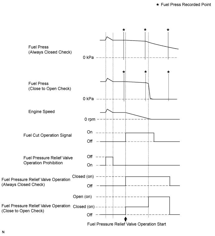
Activate the Pressure Discharge Valve Check
- HINT:
- This is the procedure for troubleshooting fuel pressure control malfunctions and combustion problems.
- Malfunctions can be determined by checking the fuel pressure when performing a fuel cut and operating the pressure discharge valve with the intelligent tester.
- During "Pressure Discharge Valve Check", the intelligent tester measures the fuel pressure while the engine is running, after the engine is stopped, and after the pressure discharge valve operates.
Connect the intelligent tester to the DLC3.
Turn the ignition switch to ON.
Turn the tester on.
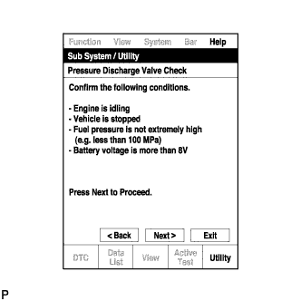
- NOTICE:
- Confirm the following conditions:
- Engine is idling.
- Vehicle is stopped.
- Fuel pressure is not extremely high (less than 100000 kPa).
- Fuel pressure sensor is normal.
- Battery voltage is more than 8 V.
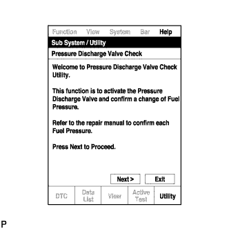
Enter the following menus: Powertrain / Engine and ECT / Utility / Pressure Discharge Valve Check.
Press "Next".
Press "Next" again to proceed.
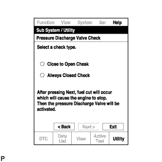
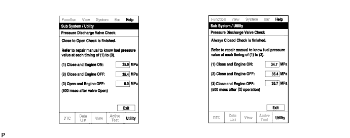
Select the "Pressure Discharge Valve Check" type.
- HINT:
- "Close to Open Check" opens the pressure discharge valve after the engine stops.
- "Always Closed Check" holds the pressure discharge valve closed during the check.
Press "Next".
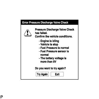
Perform troubleshooting based on the measurement results.
- HINT:
- During "Close to Open Check", if there is no large change in fuel pressure when the pressure discharge valve is closed while the engine is running and after the engine is stopped, and if the value is 0 kPa when the pressure discharge valve is open, the system is normal.
- Perform "Always Closed Check" if the value is not 0 kPa when the pressure discharge valve is open during "Close to Open Check". If the results are the same as during "Close to Open Check", there is a pressure discharge valve operation malfunction.
- If the fuel temperature is high, perform "Pressure Discharge Valve Check" after the fuel has cooled to the outside air temperature.
- If a large amount of fuel is leaking, the fuel pressure decreases when the engine is stopped. However, the condition of the pressure discharge valve can still be determined by comparing the measurement results of "Close to Open Check" and "Always Closed Check".