BLACK OUT TAPE (for Sedan) > INSTALLATION |

- HINT:
- The procedure described below is for the LH side. Use the same procedure for the RH and LH sides, unless otherwise specified.
| 1. INSTALL NO. 3 BLACK OUT TAPE |
Application precautions:
Application temperature:
- If the temperature is below 15°C (59°F), using an infrared light, heat the base (body attachment surface) and black out tape up to between 20 and 30°C (68 and 86°F). If the temperature is over 35°C (95°F), perform the operation after lowering the temperature to below 35°C (95°F).
- HINT:
- The most suitable temperature for applying the black out tape is 25°C (77°F).
- The black out tape cannot be applied correctly at low temperature due to its stiffness and weak adhesion. The tape loses its consistency at high temperature.
- If the temperature is below 15°C (59°F), using an infrared light, heat the base (body attachment surface) and black out tape up to between 20 and 30°C (68 and 86°F). If the temperature is over 35°C (95°F), perform the operation after lowering the temperature to below 35°C (95°F).
Pre-application procedure:
- Any uneven twisting or dust on the base (body attachment surface) causes a defective appearance due to air being trapped under the black out tape during application. Make sure there is no uneven twisting or dust on or around the base or black out tape.
- HINT:
- When the air is dry in winter, put cardboard between the pieces of black out tape and keep them in a dry flat place.
- Any uneven twisting or dust on the base (body attachment surface) causes a defective appearance due to air being trapped under the black out tape during application. Make sure there is no uneven twisting or dust on or around the base or black out tape.
Handling:
- Keep the black out tape in a dry flat level place because it is easily deformed.
- NOTICE:
- Do not fold, bend or expose the tape to high temperatures.
- Keep the black out tape in a dry flat level place because it is easily deformed.
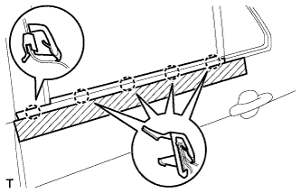
Application method (Method of squeegee operation and application for general portions):
- NOTICE:
- The positioning accuracy must be within 1 mm (0.039 in.) when starting the application, otherwise, poor appearance and adhesion will result.
- Do not reuse black out tape that has been removed. It causes deformation and weak adhesion.
- In order to suppress bubble formation, slightly raise the portion not being pressed by the squeegee away from the base. Tilt the squeegee between 40 and 50° (in the pushing direction) and between 30 and 45° (in the pulling direction), and apply 20 to 30 N (2 to 3 kg, 4 to 6 lb) of pressure at a velocity of 3 to 7 cm/sec. while pushing out the air.
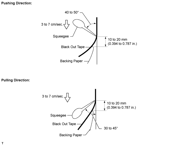
- NOTICE:
- While using the squeegee, do not change the speed, stop the operation or change the force of the application. Doing so could cause a streak across the surface of the black out tape called a shock line. While using the squeegee, keep the speed and force of application constant and the angle correct.
- HINT:
- The squeegee can be tilted in either the pushing direction or in the pulling direction against the attachment portion.
- Perform the procedure while peeling the backing paper off the black out tape, 10 to 20 mm (0.394 to 0.787 in.) from the end of the squeegee.
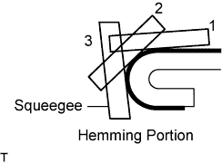
Application method (Method of squeegee operation and application method for hemming portions):
- If the tape cannot be pressed in one step using the squeegee, perform the application in several steps. Using your finger or a thicker part of the squeegee, gradually apply the tape to the small R portion of the hemming portion in 2 or 3 steps.
- HINT:
- Peel off the backing paper at the hemming portion and apply the black out tape with your finger or a thicker part of the squeegee.
- If the tape cannot be pressed in one step using the squeegee, perform the application in several steps. Using your finger or a thicker part of the squeegee, gradually apply the tape to the small R portion of the hemming portion in 2 or 3 steps.
Application method (Method of squeegee operation and application method for corner sections):
- Carefully apply the tape using a finger after peeling the backing paper off the corner section.
- In order to prevent appearance deterioration caused by the tape pin angle, turn in the tape at the corner after heating the black out tape with a dryer.
- Carefully apply the tape using a finger after peeling the backing paper off the corner section.
Inspection:
- Repeat the application using new black out tape.
- NOTICE:
- Do not use a needle to rectify bubbles in any glazed tape being applied to the outer panel, in order to make scratches virtually imperceptible.
- HINT:
- Use an instant adhesive if the hemming or corner portions of the black out tape are partially peeled off.
- Repeat the application using new black out tape.
Clean the attachment surface (Using an infrared light):
Using an infrared light, heat any black out tape and adhesive remaining on the body.
- CAUTION:
- Do not burn yourself with the heated body or infrared light.
Using a shop rag or piece of cloth, rub the remaining black out tape and adhesive off the body.
Using a non-residue solvent, clean the attachment surface.
Clean the attachment surface (Using a tape removal disc):
Set the 8 discs in the holder and insert the removal disc into an air drill or electric drill.
- NOTICE:
- Use an electric drill of which the no-load operation is 2,000 to 3,000 r/min.
Using a tape removal disc, rub the remaining black out tape and adhesive off the body.
- NOTICE:
- Wear protective glasses during the operation.
- Rotate and operate the disc in the correct direction.
- Visually check that the cutting portion is not damaged while rubbing the remaining black out tape and adhesive off the body.
Using a non-residue solvent, clean the attachment surface.
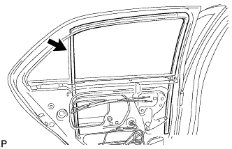
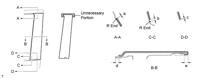
Apply new No. 3 black out tape to the positions shown in the illustration.
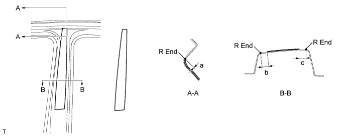
- Installation position:
Mark Measurement (along surface) a +-1 mm (+-0.039 in.) b 11 to 13 mm (0.433 to 0.512 in.) c 10 to 12 mm (0.394 to 0.472 in.)
| 2. INSTALL NO. 2 BLACK OUT TAPE |
Application precautions.
- HINT:
- Use the same procedure as for the No. 3 side.
Clean the attachment surface (Using an infrared light).
- HINT:
- Use the same procedure as for the No. 3 side.
Clean the attachment surface (Using a tape removal disc).
- HINT:
- Use the same procedure as for the No. 3 side.
Apply new No. 2 black out tape to the positions shown in the illustration.
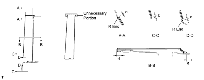
- Installation position:
Mark Measurement (along surface) a +-1 mm (+-0.039 in.) b 0 to 8 mm (0 to 0.032 in.) c 2 mm (0.079 in.) d 2 to 4 mm (0.079 to 0.157 in.) e 3 to 5 mm (0.118 to 0.197 in.)
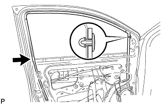
| 3. INSTALL REAR DOOR GLASS RUN |
 |
Install the rear door glass run.
| 4. INSTALL REAR DOOR BELT MOULDING |
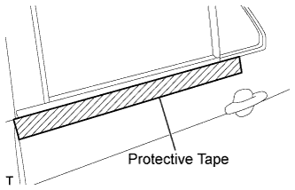
Engage the 5 claws and install a new rear door belt moulding.
 |
Remove the protective tape.
 |
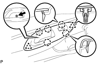
| 5. INSTALL REAR DOOR TRIM BOARD SUB-ASSEMBLY |
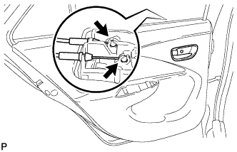 |
Connect the rear door lock remote control cable and rear door inside locking cable.
Engage the 7 clips and install the rear door trim board.
 |
Tighten the screw.
 |
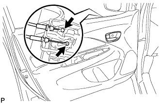
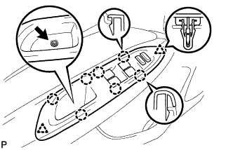
| 6. INSTALL REAR DOOR ARMREST BASE UPPER PANEL (w/ Power Window) |
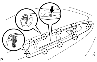 |
Connect the connector.
Engage the 7 claws and 2 clips and install the rear door armrest base upper panel.
Install the screw.
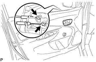
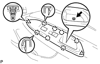
| 7. INSTALL REAR DOOR ARMREST BASE UPPER PANEL (w/o Power Window) |
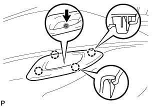 |
Engage the 4 claws and install the rear door armrest base upper panel.
Install the screw.
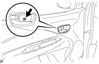
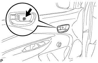
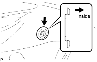
| 8. INSTALL REAR DOOR WINDOW REGULATOR HANDLE ASSEMBLY (w/o Power Window) |
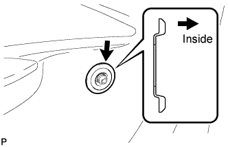 |
Install the window regulator handle plate.
Open all the windows.
Install the rear door window regulator handle with the clip at the angle shown in the illustration.
 |
| 9. INSTALL NO. 1 BLACK OUT TAPE |
Application precautions.
- HINT:
- Use the same procedure as for the No. 3 side.
Clean the attachment surface (Using an infrared light).
- HINT:
- Use the same procedure as for the No. 3 side.
Clean the attachment surface (Using a tape removal disc).
- HINT:
- Use the same procedure as for the No. 3 side.
Apply new No. 1 black out tape to the positions shown in the illustration.
- Installation position:
Mark Measurement (along surface) a +-1 mm (+-0.039 in.) b 2 mm (0.079 in.) c 0 to 1.8 mm (0 to 0.071 in.) d 3 to 5 mm (0.118 to 0.197 in.) e 2 to 4 mm (0.079 to 0.157 in.)
| 10. INSTALL FRONT DOOR GLASS RUN |
 |
Install the front door glass run, then engage the clip.
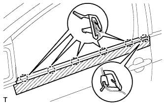
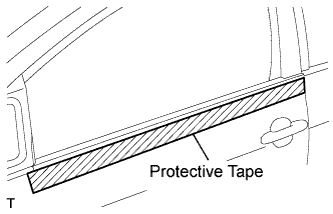
| 11. INSTALL FRONT DOOR BELT MOULDING |
Engage the 6 claws and install a new front door belt moulding.
 |
Remove the protective tape.
 |
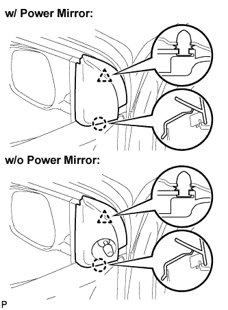
| 12. INSTALL OUTER REAR VIEW MIRROR ASSEMBLY |
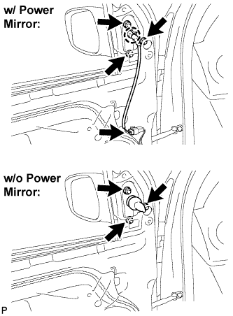 |
Engage the claw and install the outer rear view mirror with the 3 nuts.
- Torque:
- 8.0 N*m{ 82 kgf*cm , 71 in.*lbf }
w/ Power mirror:
Connect the connector.
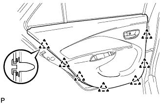
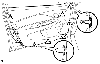
| 13. INSTALL FRONT DOOR TRIM BOARD SUB-ASSEMBLY |
w/ Power window:
Connect the front door lock remote control cable and front door inside locking cable.
Engage the 9 clips and install the front door trim board.
Tighten the screw.
 |
w/o Power window:
Connect the front door lock remote control cable and front door inside locking cable.
Engage the 9 clips and install the front door trim board.
Tighten the screw.

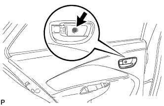
| 14. INSTALL FRONT DOOR ARMREST BASE UPPER PANEL |
 |
for Driver side with power window:
Connect the connector.
Engage the 7 claws and 2 clips and install the front armrest base upper panel.
Tighten the screw.
for Front passenger side with power window:
Connect the connector.
Engage the 7 claws and 2 clips and install the front armrest base upper panel.
Tighten the screw.
 |
w/o Power window:
Engage the 5 clips and 2 clips and install the front armrest base upper panel.
Tighten the screw.
 |
| 15. INSTALL FRONT DOOR LOWER FRAME BRACKET GARNISH |
 |
Engage the claw and clip and install the front door lower frame bracket garnish.
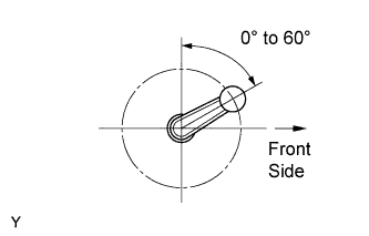
| 16. INSTALL FRONT DOOR WINDOW REGULATOR HANDLE ASSEMBLY (w/o Power Window) |
 |
Install the window regulator handle plate.
Open all the windows.
Install the front door window regulator handle with the clip at the angle shown in the illustration.
|
| 17. CONNECT CABLE TO NEGATIVE BATTERY TERMINAL |
- Torque:
- 5.4 N*m{ 55 kgf*cm , 48 in.*lbf }