OIL PUMP (for Sedan) > REMOVAL |

for Preparation Click here
- NOTICE:
- After turning the ignition switch off, waiting time may be required before disconnecting the cable from the battery terminal. Therefore, make sure to read the disconnecting the cable from the battery terminal notice before proceeding with work. (Click here)
| 1. DISCONNECT CABLE FROM NEGATIVE BATTERY TERMINAL |
| 2. REMOVE FRONT WHEEL RH |
| 3. REMOVE ENGINE UNDER COVER LH |
Remove the 3 bolts, the 4 screws and the engine under cover LH from the vehicle.
| 4. REMOVE ENGINE UNDER COVER RH |
Remove the 2 bolts, the 2 screws and the engine under cover RH from the vehicle.
| 5. DRAIN ENGINE OIL |
Remove the oil filler cap sub-assembly.
Remove the oil pan drain plug and the gasket from the No. 2 oil pan sub-assembly, and drain the engine oil into a container.
Clean and install the oil pan drain plug with a new gasket to the No. 2 oil pan sub-assembly.
- Torque:
- 38 N*m{ 382 kgf*cm , 28 ft.*lbf }
| 6. DRAIN COOLANT |
- NOTICE:
- To avoid the danger of being burned, do not remove the radiator cap sub-assembly while the engine and radiator assembly are still hot. Thermal expansion will cause hot engine coolant and steam to blow out from the radiator assembly.
Loosen the radiator drain cock plug.
Remove the radiator cap sub-assembly.
Loosen the cylinder block drain cock plug, then drain the coolant.
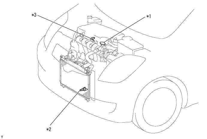
*1 Water Filler Cap Sub-assembly *2 Radiator Drain Cock Plug *3 Cylinder Block Drain Cock Plug - -
| 7. REMOVE NO. 2 CYLINDER HEAD COVER |
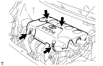 |
Remove the 4 nuts and cylinder head cover No. 2.
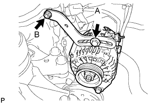
| 8. REMOVE FAN AND GENERATOR V BELT |
Loosen bolts A and B.
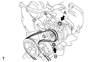 |
Release the fan and generator V belt tension and remove the fan and generator V belt.
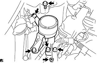
| 9. REMOVE GENERATOR ASSEMBLY |
 |
Remove the terminal cap.
Separate the connector and the harness clamp.
Remove the nut and remove terminal B.
Remove fan belt adjusting slider fixing bolts A and B and remove the fan belt adjusting slider.
 |
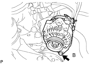
Remove fixing bolt B and remove the generator.
 |
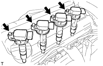
| 10. REMOVE NO. 1 IGNITION COIL |
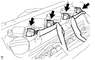 |
Disconnect the 4 ignition coil connectors.
Remove the 4 bolts and 4 ignition coils.
 |
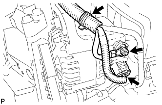
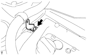
| 11. DISCONNECT VENTILATION HOSE |
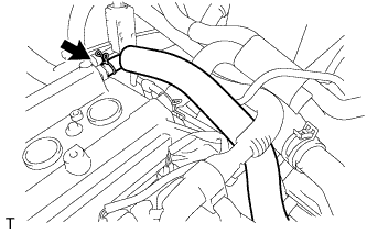 |
Disconnect the ventilation hose.
| 12. DISCONNECT FUEL VAPOR FEED HOSE ASSEMBLY |
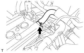 |
Disconnect fuel vapor feed hose assembly.
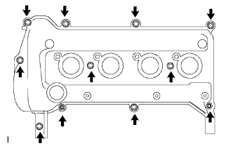
| 13. REMOVE CYLINDER HEAD COVER SUB-ASSEMBLY |
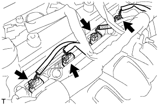 |
Disconnect the fuel injector connectors.
Disconnect the connector and 3 wire harness clamps shown in the illustration and disconnect the engine wire harness.
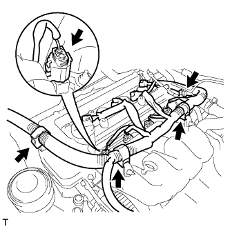 |
Remove the bolt and remove the wire harness bracket.
 |
Remove the 9 bolts, 2 nuts and 2 seal washers and then remove the cylinder head cover sub-assembly.
 |
Remove the gasket from the cylinder head cover sub-assembly.
| 14. REMOVE ENGINE MOUNTING INSULATOR SUB-ASSEMBLY RH |
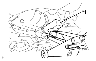 |
Place a wooden block on a jack underneath the oil pan sub-assembly.
Text in Illustration *1 Wooden Block - NOTICE:
- To prevent the No. 2 oil pan sub-assembly from deforming, do not place any attachments onto the No. 2 oil pan sub-assembly.
Remove the 5 bolts, the nut and the engine mounting insulator sub-assembly RH from the transverse engine engine mounting bracket and the vehicle.
 |
| 15. REMOVE CRANKSHAFT DAMPER SUB-ASSEMBLY |
 |
Set the No. 1 cylinder to TDC/compression.
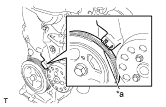
Turn the crankshaft damper sub-assembly, and align its timing notch with timing mark "0" of the oil pump assembly.
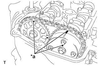
Text in Illustration *a Timing Mark Check that the timing marks on the camshaft timing sprocket and the camshaft timing gear assembly are all facing upward as shown in the illustration.
If not, turn the crankshaft 1 complete revolution (360°) and align the marks as above.Text in Illustration *a Timing Mark
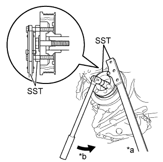
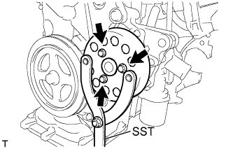
Using SST, loosen the bolt while holding the crankshaft damper sub-assembly.
Text in Illustration *a Hold *b Turn - SST
- 09213-58014
(90201-08131, 91111-50845)
09330-00021 (09330-00030)
- NOTICE:
- Check the SST installation positions when installing them, to avoid the SST fixing bolts from coming into contact with the oil pump assembly.
 |
Remove the SST and the bolt.
Remove the crankshaft damper sub-assembly from the crankshaft.
| 16. REMOVE CRANKSHAFT POSITION SENSOR |
 |
Disconnect the crankshaft position sensor connector.
Remove the bolt and remove the crankshaft position sensor.
| 17. REMOVE CAMSHAFT TIMING OIL CONTROL VALVE ASSEMBLY |
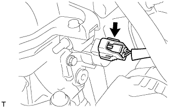 |
Disconnect the camshaft timing oil control valve assembly connector.
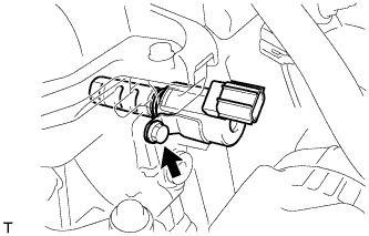
Remove the bolt and nut and remove the camshaft timing oil control valve assembly.
 |
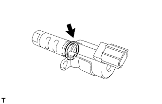
Remove the O-ring from the camshaft timing oil control valve assembly.
 |
| 18. REMOVE WATER PUMP PULLEY |
 |
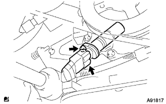
Using SST, hold the water pump pulley.
- SST
- 09960-10010
(09962-01000, 09963-00700)
Remove the 3 bolts and remove the water pump pulley.
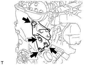
| 19. REMOVE ENGINE WATER PUMP ASSEMBLY |
 |
Remove the 3 bolts and 2 nuts and remove the engine water pump assembly and gasket.
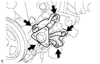
| 20. REMOVE TRANSVERSE ENGINE ENGINE MOUNTING BRACKET |
 |
Remove the 4 bolts and the transverse engine engine mounting bracket from the oil pump assembly.
| 21. REMOVE OIL PUMP ASSEMBLY |
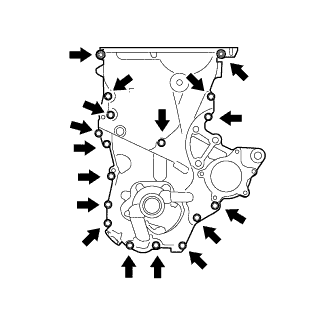 |
Remove the 16 bolts and the nut from the oil pump assembly.
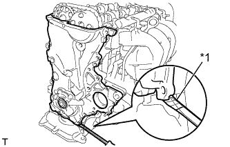
Using a screwdriver with its tip wrapped in protective tape, remove the oil pump assembly by prying between the cylinder head sub-assembly and cylinder block sub-assembly.
Text in Illustration *1 Protective Tape - NOTICE:
- Do not damage the contact surfaces of the oil pump assembly and oil pan sub-assembly.
 |
Remove the 2 O-rings from the cylinder block sub-assembly and the oil pan sub-assembly.
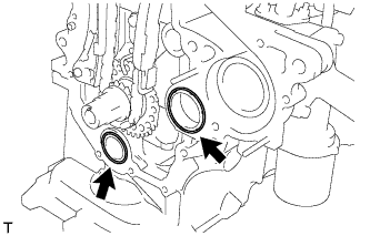 |