MANUAL TRANSAXLE ASSEMBLY (for Hatchback) > REMOVAL |

| 1. DRAIN TRANSAXLE OIL |
Remove the manual transmission filler plug and the gasket.
Remove the drain plug sub-assembly and gasket, and then drain the manual transaxle oil.
Install a new gasket and the drain plug sub-assembly.
- Torque:
- 39 N*m{ 400 kgf*cm , 29 ft.*lbf }
| 2. REMOVE FRONT WIPER MOTOR AND LINK |
| 3. REMOVE FRONT NO.1 VENTILATOR SEAL |
 |
Disengage the clamp and remove the front No. 1 ventilator seal.
| 4. REMOVE FRONT AIR SHUTTER SEAL RH |
- HINT:
- Use the same procedure as for the No. 1 ventilator seal.
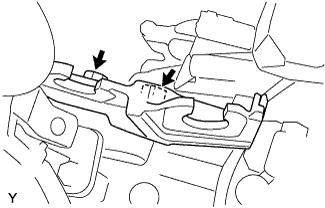
| 5. REMOVE INNER COWL TOP TO COWL BRACE |
 |
Remove the 2 bolts and the inner cowl top to cowl brace.
| 6. REMOVE OUTER COWL TOP PANEL |
 |
Disengage the 2 clamps and separate the wire harness.
Remove the 8 bolts and the outer cowl top panel.
| 7. REMOVE BATTERY |
Disconnect the cable from the battery terminal.
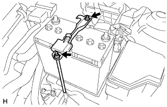 |
Loosen the 2 nuts and remove the battery clamp.
Remove the battery.
| 8. REMOVE BATTERY TRAY |
| 9. REMOVE BATTERY CARRIER |
Disengage the 6 clamps and disconnect the wire harness from the battery carrier.
 |
Remove the 5 bolts and the battery carrier.
| 10. REMOVE AIR CLEANER ASSEMBLY |
Disengage the clamp and disconnect the fuel vapor feed hose assembly from the No. 1 air cleaner hose.
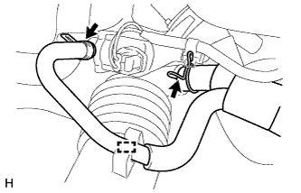 |
Loosen the 2 hose clamps and disconnect the fuel vapor feed hose assembly from the No. 1 air cleaner hose and vacuum switching valve assembly.
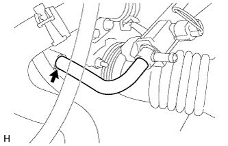
Disconnect the No. 2 fuel vapor feed hose from the intake manifold.
 |
Disengage the 2 clamps and disconnect the wire harness from the air cleaner cap sub-assembly and vacuum switching valve assembly.
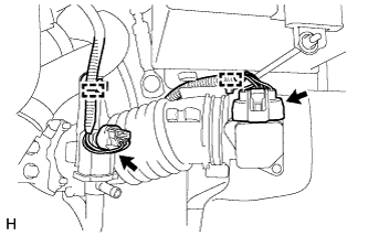 |
Disconnect the mass air flow meter connector.
Disconnect the vacuum switching valve connector.
Loosen the hose clamp and disconnect the No. 1 air cleaner hose from the throttle with motor body assembly.
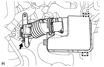 |
Disengage the 2 clamps and remove the air cleaner cap sub-assembly with No. 1 air cleaner hose.
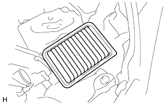
Remove the air cleaner element.
 |
Disengage the clamp and disconnect the wire harness from the air cleaner case.
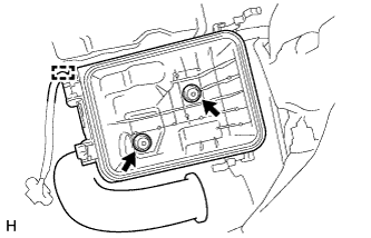 |
Remove the 2 bolts and the air cleaner case from the air cleaner bracket.
| 11. REMOVE AIR CLEANER BRACKET |
Disengage the clamp and disconnect the wire harness from the air cleaner bracket.
 |
Remove the 2 bolts and the air cleaner bracket.
| 12. REMOVE STARTER ASSEMBLY (for Cold Area Specification Vehicles) |
| 13. REMOVE STARTER ASSEMBLY (except Cold Area Specification Vehicles) |
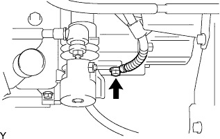
| 14. SEPARATE CLUTCH RELEASE CYLINDER ASSEMBLY |
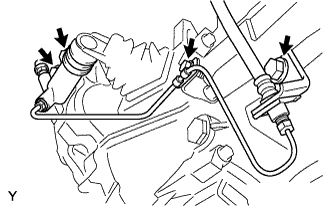 |
Remove the 4 bolts, then separate the clutch release cylinder assembly.
- HINT:
- Suspend the clutch release cylinder assembly with a piece of rope so as not to overload the clutch pipe.
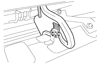
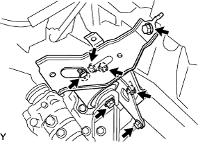
| 15. SEPARATE TRANSMISSION CONTROL CABLE ASSEMBLY |
Remove the clip A and washer, and separate the control shift cable from the manual transaxle assembly.
Text in Illustration *1 Control Shift Cable *2 Control Select Cable *3 Clip A *4 Clip B
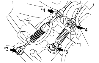 |
Remove the clip B from the control shift cable, and separate the control shift cable from the shift cable bracket.
Remove the clip A and washer, and separate the control select cable from the manual transaxle assembly.
Remove the clip B from the control select cable, and separate the control select cable from the shift cable bracket.
| 16. REMOVE CONTROL CABLE BRACKET |
 |
Remove the 2 bolts and the control cable bracket.
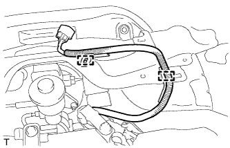
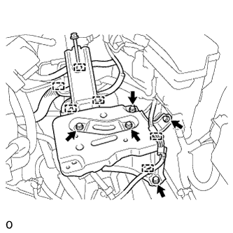
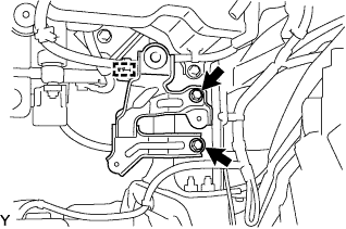
| 17. DISCONNECT WIRE HARNESS (w/ ABS) |
Separate the 4 clamps and remove the bolt, and separate the wire harness from the manual transaxle assembly.
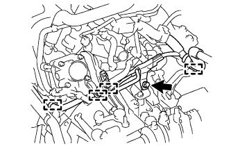 |
Remove the bolt and separate the ground wire.
 |
Disconnect the back up light switch connector.
| 18. DISCONNECT WIRE HARNESS (w/o ABS) |
Separate the 4 clamps and remove the bolt, and separate the wire harness from the manual transaxle assembly.
|
Remove the bolt and separate the ground wire.
|
Disconnect the back up light switch connector.
Disconnect the speedometer sensor connector.
| 19. REMOVE FRONT SUSPENSION CROSSMEMBER SUB-ASSEMBLY |
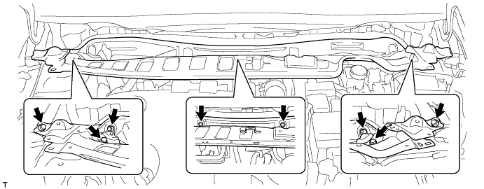
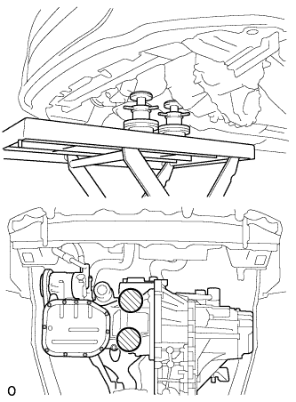
| 20. SUPPORT ENGINE AND TRANSAXLE |
On a flat location, set the attachment, plate lift attachment, and wooden block in the positions shown in the figure, and set the engine assembly.
Text in Illustration 
Attachment Placement Positions - NOTICE:
- Set the engine assembly with transaxle so that it is horizontal.
- Never attach the attachment and plate lift attachment to the oil pan section of the manual transaxle.
 |
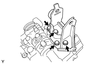
| 21. REMOVE TRANSVERSE ENGINE ENGINE MOUNTING CONTROL BRACKET |
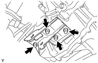 |
Remove the 4 bolts and the transverse engine engine mounting control bracket.
| 22. SUPPORT MANUAL TRANSAXLE ASSEMBLY |
Support the manual transaxle assembly with a transmission jack so that it is stable.
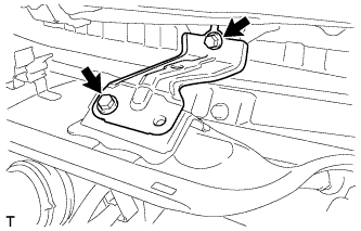
| 23. REMOVE TRANSVERSE ENGINE ENGINE MOUNTING INSULATOR |
 |
Remove the bolt and nut, then separate the transverse engine engine mounting insulator from the transverse engine engine mounting bracket.
- HINT:
- Hold the nut and loosen the bolt.
Remove the 5 bolts and the transverse engine engine mounting insulator.
| 24. REMOVE TRANSVERSE ENGINE ENGINE MOUNTING BRACKET |
 |
Remove the 4 bolts and the transverse engine engine mounting bracket from the manual transaxle assembly.
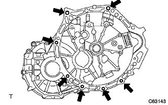
| 25. REMOVE MANUAL TRANSAXLE ASSEMBLY |
Remove the 7 bolts and the manual transaxle assembly.
- NOTICE:
- To prevent damage to the knock pins, do not pry between the transaxle and engine.
- To avoid damage to the input shaft, do not forcefully shake the manual transaxle.
 |
| 26. REMOVE SPEEDOMETER DRIVEN HOLE COVER SUB-ASSEMBLY (w/ ABS) |
Remove the bolt and speedometer driven hole cover sub-assembly from the manual transaxle assembly.
Remove the O-ring from the speedometer driven hole cover sub-assembly.
| 27. REMOVE SPEEDOMETER SENSOR (w/o ABS) |
Remove the bolt and speedometer sensor from the manual transaxle assembly.
Remove the E-ring and speedometer driven gear from the speedometer sensor.
Text in Illustration *1 Speedometer Driven Gear *2 O-ring *3 E-ring
 |
Remove the O-ring from the speedometer sensor.
| 28. REMOVE WIRE HARNESS CLAMP BRACKET |
Remove the 3 bolts and 3 wire harness clamp brackets from the manual transaxle assembly.
 |