POWER WINDOW CONTROL SYSTEM (for Sedan) > Front Passenger Side Power Window does not Operate with Front Passenger Side Power Window Switch |

DESCRIPTION
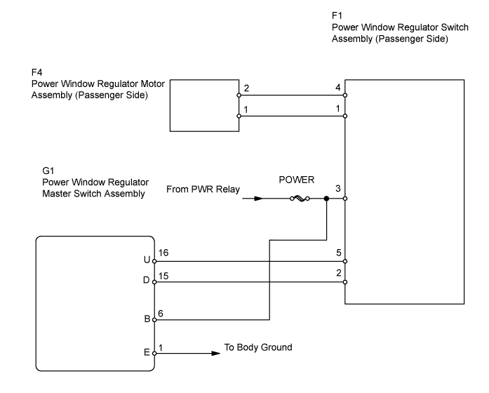
If the passenger side manual UP / DOWN function does not operate, a malfunction may exist in the power window regulator motor, power window regulator switch, power window regulator master switch or wire harness.WIRING DIAGRAM
INSPECTION PROCEDURE
| 1.CHECK POWER WINDOW REGULATOR SWITCH ASSEMBLY (PASSENGER SIDE) (POWER SOURCE) |
Disconnect the F1 power window regulator switch assembly connector.
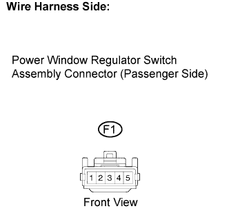 |
Measure the voltage of the wire harness side connector.
- Standard voltage:
Tester Connection Condition Specified Condition F1-3 - Body ground Ignition switch ON 11 to 14 V
Reconnect the F1 power window regulator switch assembly connector.
|
| ||||
| OK | |
| 2.INSPECT POWER WINDOW REGULATOR SWITCH ASSEMBLY (PASSENGER SIDE) |
Remove the power window regulator switch assembly.
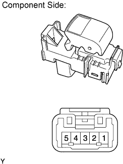 |
Measure the resistance of the switch when the switch is operated.
- Standard resistance:
Tester Connection Switch Condition Specified Condition 3 - 4
2 - 1UP Below 1 Ω 5 - 4
2 - 1OFF Below 1 Ω 5 - 4
3 - 1DOWN Below 1 Ω
Reinstall the power window regulator switch assembly.
|
| ||||
| OK | |
| 3.CHECK HARNESS AND CONNECTOR (SWITCH (PASSENGER SIDE) - MOTOR (PASSENGER SIDE)) |
Disconnect the F1 power window regulator switch assembly connector.
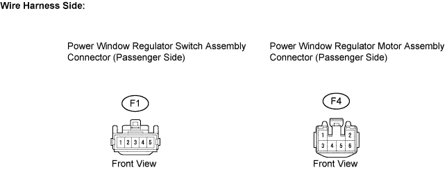
Disconnect the F4 power window regulator motor assembly connector.
Measure the resistance of the wire harness side connectors.
- Standard resistance:
Tester Connection Specified Condition F1-1 - F4-1 Below 1 Ω F1-4 - F4-2 Below 1 Ω F1-1 or F4-1 - Body ground 10 kΩ or higher F1-4 or F4-2 - Body ground 10 kΩ or higher
Reconnect the F1 power window regulator switch assembly connector.
Reconnect the F4 power window regulator motor assembly connector.
|
| ||||
| OK | |
| 4.INSPECT POWER WINDOW REGULATOR MOTOR ASSEMBLY (PASSENGER SIDE) |
Remove the power window regulator motor assembly.
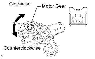 |
Apply battery voltage to connector terminals 1 and 2.
- NOTICE:
- Do not apply battery voltage to any terminals except terminals 1 and 2.
Check that the motor gear rotates smoothly as follows.
- OK:
Measurement Condition Specified Condition Battery positive (+) → 1
Battery negative (-) → 2Motor gear rotates clockwise Battery positive (+) → 2
Battery negative (-) → 1Motor gear rotates counterclockwise
Reinstall the power window regulator motor assembly.
|
| ||||
| OK | |
| 5.CHECK HARNESS AND CONNECTOR (MASTER SWITCH - SWITCH (PASSENGER SIDE)) |
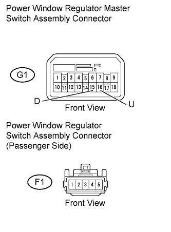
Disconnect the G1 power window regulator master switch assembly connector.
 |
Disconnect the F1 power window regulator switch assembly connector.
Measure the resistance of the wire harness side connectors.
- Standard resistance:
Tester Connection Specified Condition G1-16 (U) - F1-5 Below 1 Ω G1-15 (D) - F1-2 Below 1 Ω G1-16 (U) or F1-5 - Body ground 10 kΩ or higher G1-15 (D) or F1-2 - Body ground 10 kΩ or higher
Reconnect the G1 power window regulator master switch assembly connector.
Reconnect the F1 power window regulator switch assembly connector.
|
| ||||
| OK | |
| 6.INSPECT POWER WINDOW REGULATOR MASTER SWITCH ASSEMBLY (FRONT PASSENGER SWITCH) |
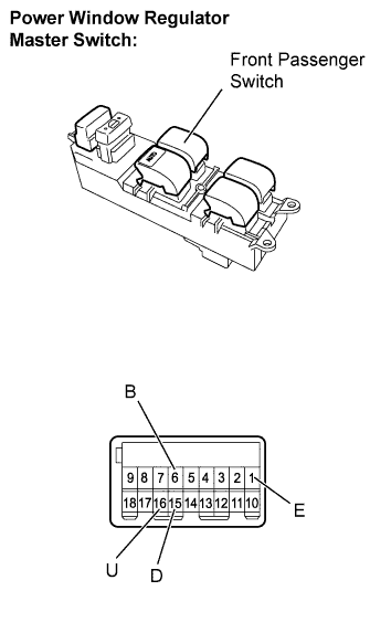 |
Remove the power window regulator master switch.
Measure the resistance of the switch when the switch is operated.
- Standard resistance:
Window Lock Switch Condition Power Window Switch Condition Tester Connection Specified Condition OFF UP 1 (E) - 15 (D)
6 (B) - 16 (U)Below 1 Ω OFF OFF 1 (E) - 16 (U)
1 (E) - 15 (D)Below 1 Ω OFF DOWN 1 (E) - 16 (U)
6 (B) - 15 (D)Below 1 Ω ON UP 1 (E) - 15 (D) 10 kΩ or higher 6 (B) - 16 (U) Below 1 Ω ON OFF 15 (D) - 16 (U) Below 1 Ω ON DOWN 1 (E) - 16 (U) 10 kΩ or higher 6 (B) - 15 (D) Below 1 Ω
Reinstall the power window regulator master switch.
|
| ||||
| OK | ||
| ||