DTC B1771 Passenger Side Buckle Switch Circuit Malfunction |

DESCRIPTION
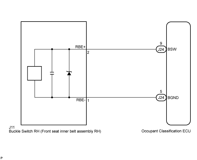
The passenger side buckle switch circuit consists of the occupant classification ECU and the front seat inner belt assembly RH.DTC B1771 is recorded when a malfunction is detected in the passenger side buckle switch circuit.
Troubleshoot DTC B1771 first when DTCs B1771 and B1795 are output simultaneously.
| DTC No. | DTC Detecting Condition | Trouble Area |
| B1771 |
|
|
WIRING DIAGRAM
INSPECTION PROCEDURE
- HINT:
- If troubleshooting (wire harness inspection) is difficult to perform, remove the front passenger seat installation bolts to see the under surface of the seat cushion.
- In the above case, hold the seat so that it does not tip over. Holding the seat for a long period of time may cause a problem, such as seat rail deformation. Hold the seat up only for as long as necessary.
| 1.CHECK DTC |
Turn the ignition switch to the on position.
Clear the DTCs stored in the memory (Click here).
- HINT:
- First clear DTCs stored in the occupant classification ECU and then in the center airbag sensor assembly.
Turn the ignition switch to the lock position.
Turn the ignition switch to the on position.
Check the DTCs (Click here).
- OK:
- DTC B1771 is not output.
- HINT:
- Codes other than DTC B1771 may be output at this time, but they are not related to this check.
|
| ||||
| NG | |
| 2.CHECK CONNECTION OF CONNECTORS |
Turn the ignition switch to the lock position.
Disconnect the negative (-) terminal cable from the battery, and wait for at least 90 seconds.
Check that the connectors are properly connected to the occupant classification ECU and the front seat inner belt assembly RH.
- OK:
- The connectors are properly connected.
|
| ||||
| OK | |
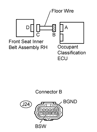
| 3.CHECK FLOOR WIRE (TO B+) |
Disconnect the connectors from the occupant classification ECU and the front seat inner belt assembly RH.
 |
Connect the negative (-) terminal cable to the battery.
Turn the ignition switch to the on position.
Measure the voltage.
- Standard voltage:
Tester connection Condition Specified condition J24-9 (BSW) -
Body groundIgnition switch on Below 1 V J24-5 (BGND) -
Body groundIgnition switch on Below 1 V
|
| ||||
| OK | |
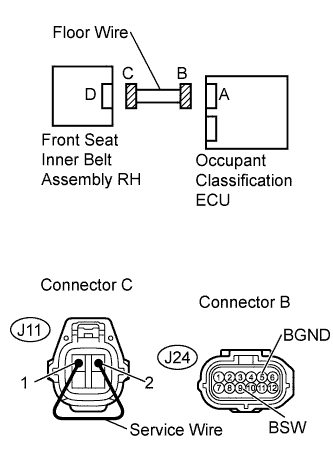
| 4.CHECK FLOOR WIRE (FOR OPEN) |
Turn the ignition switch to the lock position.
 |
Disconnect the negative (-) terminal cable from the battery, and wait for at least 90 seconds.
Using a service wire, connect J11-2 and J11-1 of connector C.
- NOTICE:
- Do not forcibly insert the service wire into the terminals of the connector when connecting.
Measure the resistance.
- Standard resistance:
Tester connection Condition Specified condition J24-9 (BSW) -
J24-5 (BGND)Always Below 1 Ω
|
| ||||
| OK | |
| 5.CHECK FLOOR WIRE (FOR SHORT) |
Disconnect the service wire from connector C.
|
Measure the resistance.
- Standard resistance:
Tester connection Condition Specified condition J24-9 (BSW) -
J24-5 (BGND)Always 1 MΩ or higher
|
| ||||
| OK | |
| 6.CHECK FLOOR WIRE (TO GROUND) |
Measure the resistance.
- Standard resistance:
Tester connection Condition Specified condition J24-9 (BSW) -
Body groundAlways 1 MΩ or higher J24-5 (BGND) -
Body groundAlways 1 MΩ or higher
|
|
| ||||
| OK | |
| 7.CHECK DTC |
Connect the connectors to the occupant classification ECU and the front seat inner belt assembly RH.
Connect the negative (-) terminal cable to the battery.
Turn the ignition switch to the on position.
Clear the DTCs stored in the memory (Click here).
- HINT:
- First clear DTCs stored in the occupant classification ECU and then in the center airbag sensor assembly.
Turn the ignition switch to the lock position.
Turn the ignition switch to the on position.
Check the DTCs (Click here).
- OK:
- DTC B1771 is not output.
- HINT:
- Codes other than DTC B1771 may be output at this time, but they are not related to this check.
|
| ||||
| NG | |
| 8.REPLACE FRONT SEAT INNER BELT ASSEMBLY RH |
Turn the ignition switch to the lock position.
Disconnect the negative (-) terminal cable from the battery, and wait for at least 90 seconds.
Replace the front seat inner belt assembly RH (Click here ).
- HINT:
- Perform the inspection using parts from a normal vehicle if possible.
Connect the negative (-) terminal cable to the battery.
Turn the ignition switch to the on position.
Clear the DTCs stored in the memory (Click here).
- HINT:
- First clear DTCs stored in the occupant classification ECU and then in the center airbag sensor assembly.
Turn the ignition switch to the lock position.
Turn the ignition switch to the on position.
Check the DTCs (Click here).
- OK:
- DTC B1771 is not output.
- HINT:
- Codes other than DTC B1771 may be output at this time, but they are not related to this check.
|
| ||||
| NG | |
| 9.REPLACE OCCUPANT CLASSIFICATION ECU |
Turn the ignition switch to the lock position.
Disconnect the negative (-) terminal cable from the battery, and wait for at least 90 seconds.
Replace the occupant classification ECU (Click here).
| NEXT | |
| 10.PERFORM ZERO POINT CALIBRATION |
Connect the negative (-) terminal cable to the battery.
Connect the Techstream to the DLC3.
Turn the ignition switch to the on position.
Using the Techstream, perform the zero point calibration (Click here).
- OK:
- COMPLETED is displayed on the tester.
| NEXT | |
| 11.PERFORM SENSITIVITY CHECK |
Using the Techstream, perform the sensitivity check (Click here).
Confirm that nothing is placed on the passenger seat.
Confirm that the beginning sensor reading is within the standard range.
- Standard range:
- -3.2 to 3.2 kg (-7 to 7 lb)
Place a 30 kg (66.14 lb) weight (e.g. a lead mass) onto the front passenger seat.
Confirm that the sensitivity is within the standard range.
- Standard range:
- 27 to 33 kg (59.52 to 72.75 lb)
- HINT:
- When performing the sensitivity check, use a solid metal weight (the check result may not be accurate if a liquid weight is used).
| NEXT | ||
| ||