NAVIGATION SYSTEM (for SD) > Speaker Circuit |

for Preparation Click here
DESCRIPTION
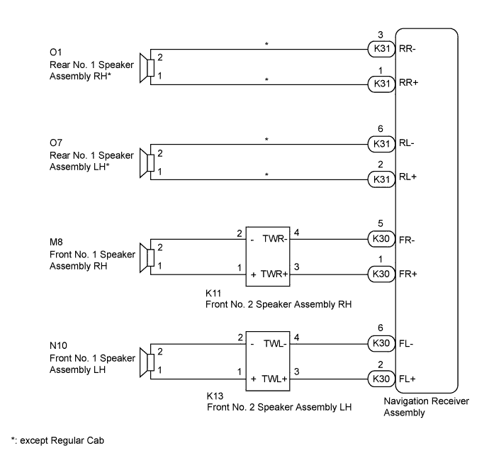
The navigation receiver assembly sends sound signals to the speaker.WIRING DIAGRAM
INSPECTION PROCEDURE
| 1.CHECK SPEAKER |
Check the malfunctioning speakers.
Result Result Proceed to Malfunction in front speaker area A Malfunction in rear speaker area* B - *: except Regular Cab
- *: except Regular Cab
|
| ||||
| A | |
| 2.CHECK FRONT SIDE SPEAKER |
Check the malfunctioning speakers.
Result Result Proceed to Malfunction in front No. 2 speaker assembly A Malfunction in front No. 1 speaker assembly B
|
| ||||
| A | |
| 3.INSPECT FRONT NO. 2 SPEAKER ASSEMBLY |
Temporarily replace the front No. 2 speaker assembly with a new or normally functioning one.
- for Regular Cab: Click here
- for Double Cab: Click here
- for CrewMax: Click here
- for Regular Cab: Click here
Check that the speaker sounds normally.
- OK:
- Malfunction disappears.
Result Result Proceed to OK A NG (for Regular Cab) B NG (for Double Cab) C NG (for CrewMax) D
|
| ||||
|
| ||||
|
| ||||
| A | |
| 4.CHECK HARNESS AND CONNECTOR (NAVIGATION RECEIVER ASSEMBLY - FRONT NO. 2 SPEAKER ASSEMBLY) |
Disconnect the K30 navigation receiver assembly connector.
Disconnect the K11*1 and/or K13*2 front No. 2 speaker assembly connector.
- *1: for RH
- *2: for LH
- *1: for RH
Measure the resistance according to the value(s) in the table below.
- Standard Resistance:
- for RH:
Tester Connection Condition Specified Condition K30-1 (FR+) - K11-3 (TWR+) Always Below 1 Ω K30-5 (FR-) - K11-4 (TWR-) Always Below 1 Ω K30-1 (FR+) - Body ground Always 10 kΩ or higher K30-5 (FR-) - Body ground Always 10 kΩ or higher - for LH:
Tester Connection Condition Specified Condition K30-2 (FL+) - K13-3 (TWL+) Always Below 1 Ω K30-6 (FL-) - K13-4 (TWL-) Always Below 1 Ω K30-2 (FL+) - Body ground Always 10 kΩ or higher K30-6 (FL-) - Body ground Always 10 kΩ or higher
Result Result Proceed to OK (for Column Shift Type) A OK (for Floor Shift Type) B NG C
|
| ||||
|
| ||||
| A | ||
| ||
| 5.INSPECT FRONT NO. 1 SPEAKER ASSEMBLY |
Disconnect the M8*1 and/or N10*2 front No. 1 speaker assembly connector.
- *1: for RH
- *2: for LH
- *1: for RH
 |
Measure the resistance according to the value(s) in the table below.
- Standard Resistance:
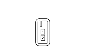
Tester Connection Condition Specified Condition 1 - 2 Always 3.2 to 4.8 Ω
Result Result Proceed to OK A NG (for Regular Cab) B NG (for Double Cab) C NG (for CrewMax) D
|
| ||||
|
| ||||
|
| ||||
| A | |
| 6.CHECK HARNESS AND CONNECTOR (FRONT NO. 2 SPEAKER ASSEMBLY - FRONT NO. 1 SPEAKER ASSEMBLY) |
- *1: for RH
- *2: for LH
Disconnect the K11*1 and/or K13*2 front No. 2 speaker assembly connector.
Disconnect the M8*1 and/or N10*2 front No. 1 speaker assembly connector.
Measure the resistance according to the value(s) in the table below.
- Standard Resistance:
- for RH:
Tester Connection Condition Specified Condition K11-1 (+) - M8-1 Always Below 1 Ω K11-2 (-) - M8-2 Always Below 1 Ω K11-1 (+) - Body ground Always 10 kΩ or higher K11-2 (-) - Body ground Always 10 kΩ or higher - for LH:
Tester Connection Condition Specified Condition K13-1 (+) - N10-1 Always Below 1 Ω K13-2 (-) - N10-2 Always Below 1 Ω K13-1 (+) - Body ground Always 10 kΩ or higher K13-2 (-) - Body ground Always 10 kΩ or higher
Result Result Proceed to OK (for Column Shift Type) A OK (for Floor Shift Type) B NG C
|
| ||||
| OK | |
| 7.INSPECT FRONT NO. 2 SPEAKER ASSEMBLY |
Disconnect the K11*1 and/or K13*2 front No. 2 speaker assembly connector.
- *1: for RH
- *2: for LH
- *1: for RH
 |
Measure the resistance according to the value(s) in the table below.
- Standard Resistance:
- for RH:
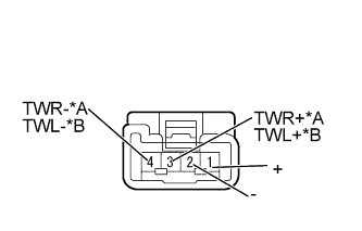
Tester Connection Condition Specified Condition 1 (+) - 3 (TWR+) Always Below 1 Ω 2 (-) - 4 (TWR-) Always Below 1 Ω - for LH:
Tester Connection Condition Specified Condition 1 (+) - 3 (TWL+) Always Below 1 Ω 2 (-) - 4 (TWL-) Always Below 1 Ω
Text in Illustration *A for RH *B for LH Result Result Proceed to OK (for Column Shift Type) A OK (for Floor Shift Type) B NG (for Regular Cab) C NG (for Double Cab) D NG (for CrewMax) E
|
| ||||
|
| ||||
|
| ||||
|
| ||||
| A | ||
| ||
| 8.INSPECT REAR NO. 1 SPEAKER ASSEMBLY |
Disconnect the O1*1 and/or O7*2 rear No. 1 speaker assembly connector.
- *1: for RH
- *2: for LH
- *1: for RH
|
Measure the resistance according to the value(s) in the table below.
- Standard Resistance:
Tester Connection Condition Specified Condition 1 - 2 Always 3.2 to 4.8 Ω
Result Result Proceed to OK A NG (for Double Cab) B NG (for CrewMax) C
|
| ||||
|
| ||||
| A | |
| 9.CHECK HARNESS AND CONNECTOR (NAVIGATION RECEIVER ASSEMBLY - REAR NO. 1 SPEAKER ASSEMBLY) |
Disconnect the K31 navigation receiver assembly connector.
Disconnect the O1*1 and/or O7*2 rear No. 1 speaker assembly connector.
- *1: for RH
- *2: for LH
- *1: for RH
Measure the resistance according to the value(s) in the table below.
- Standard Resistance:
- for RH:
Tester Connection Condition Specified Condition K31-1 (RR+) - O1-1 Always Below 1 Ω K31-3 (RR-) - O1-2 Always Below 1 Ω K31-1 (RR+) - Body ground Always 10 kΩ or higher K31-3 (RR-) - Body ground Always 10 kΩ or higher - for LH:
Tester Connection Condition Specified Condition K31-2 (RL+) - O7-1 Always Below 1 Ω K31-6 (RL-) - O7-2 Always Below 1 Ω K31-2 (RL+) - Body ground Always 10 kΩ or higher K31-6 (RL-) - Body ground Always 10 kΩ or higher
Result Result Proceed to OK (for Column Shift Type) A OK (for Floor Shift Type) B NG C
|
| ||||
|
| ||||
| A | ||
| ||