AUTOMATIC TRANSMISSION ASSEMBLY > INSTALLATION |

for Preparation Click here
| 1. INSTALL TORQUE CONVERTER CLUTCH ASSEMBLY |
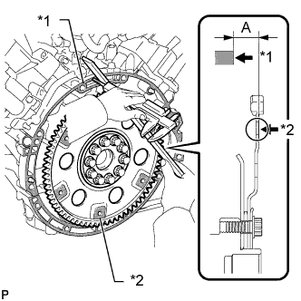 |
Using a vernier caliper and straightedge, measure dimension "A" between the transmission fitting surface of the engine*1 and the torque converter fitting surface of the drive plate*2 (step 1).
Align the matchmarks on the transmission case and torque converter clutch, and then mesh the splines of the input shaft and turbine runner.
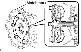 |
Mesh the splines of the stator shaft and stator while turning the torque converter clutch.
- HINT:
- Turn the torque converter clutch approximately 180°.
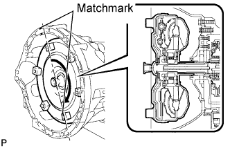 |
Turn the torque converter clutch and align the matchmarks on the torque converter clutch and transmission case to fit the key of the oil pump drive gear into the slot on the torque converter clutch.
- NOTICE:
- Do not push on the torque converter when aligning the matchmarks.
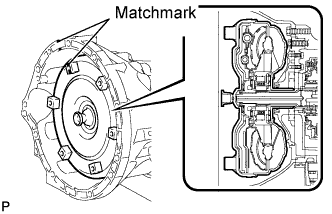 |
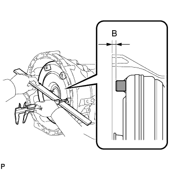
Using a vernier caliper and straightedge, measure dimension "B" shown in the illustration and check that B is more than A (measured in step 1).
- Standard distance:
- A + 1 mm (0.0394 in.) or more
 |
| 2. INSTALL TRANSFER ASSEMBLY |
Install the transfer (Click here).
| 3. INSTALL TRANSMISSION CONTROL CABLE BRACKET |
Install the bracket with the 2 bolts.
- Torque:
- 12 N*m{ 122 kgf*cm , 9 ft.*lbf }
| 4. INSTALL WIRE HARNESS CLAMP BRACKET |
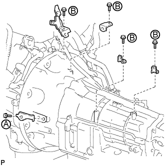 |
Install the 5 wire harness clamp brackets with the 5 bolts.
- Torque:
- for bolt A:
- 60 N*m{ 612 kgf*cm , 44 ft.*lbf }
- Torque:
- for bolt B:
- 8.0 N*m{ 82 kgf*cm , 71 in.*lbf }
| 5. INSTALL AUTOMATIC TRANSMISSION ASSEMBLY |
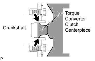 |
Apply clutch spline grease to the surface of the torque converter clutch centerpiece that contacts the crankshaft.
- Clutch spline grease:
- Toyota Genuine Clutch Spline Grease or equivalent
- Maximum grease amount:
- Approximately 1 g (0.0353 oz.)
Confirm that the 2 knock pins are on the transmission contact surface of the engine block before transmission installation.
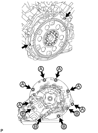 |
Install the transmission with the 10 bolts.
- Torque:
- for 17 mm head bolt A:
- 71 N*m{ 724 kgf*cm , 52 ft.*lbf }
- for 14 mm head bolt B:
- 37 N*m{ 377 kgf*cm , 27 ft.*lbf }
| 6. INSTALL TRANSMISSION OIL COOLER ASSEMBLY (w/ Trailer Towing System) |
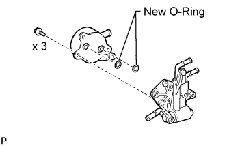 |
Coat 2 new O-rings with ATF and install them to the grooves of the transmission oil cooler.
Install the oil cooler to the transmission oil thermostat with the 3 bolts.
- Torque:
- 14 N*m{ 143 kgf*cm , 10 ft.*lbf }
Install the 2 No. 1 transmission oil cooler hoses to the transmission oil thermostat.
- NOTICE:
- Make sure the pinching portion of each clip is facing the direction shown in the illustration.
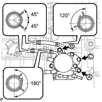 |
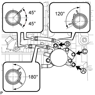
Connect the 2 No. 1 transmission oil cooler hoses to the transmission.
- NOTICE:
- Make sure the pinching portion of each clip is facing the direction shown in the illustration.
Temporarily install the transmission oil cooler together with the transmission oil thermostat with bolt C. Temporarily install bolt A and bolt B. Tighten the bolts in alphabetical order.
- Torque:
- 21 N*m{ 214 kgf*cm , 15 ft.*lbf }
Connect the No. 2 transmission oil cooler inlet hose and No. 2 transmission oil cooler outlet hose to the oil cooler tube.
- NOTICE:
- When connecting the hoses to the tube, support the tube by hand and be careful to prevent the tube from being deformed.
- Make sure the paint marks and pinching portion of each clip are facing the directions shown in the illustration.
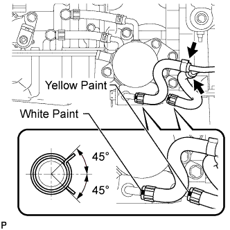 |
Install the No. 2 transmission oil cooler inlet hose and No. 2 transmission oil cooler outlet hose to the transmission oil thermostat.
- NOTICE:
- Make sure the paint marks and pinching portion of each clip are facing the directions shown in the illustration.
| 7. INSTALL TRANSMISSION OIL COOLER ASSEMBLY (w/o Trailer Towing System) |
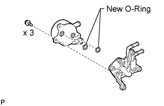 |
Coat 2 new O-rings with ATF and install them to the grooves of the transmission oil cooler.
Install the transmission oil cooler to the transmission oil cooler spacer with the 3 bolts.
- Torque:
- 14 N*m{ 143 kgf*cm , 10 ft.*lbf }
Install the 2 No. 1 transmission oil cooler hoses to the transmission oil cooler spacer.
- NOTICE:
- Make sure the pinching portion of each clip is facing the direction shown in the illustration.
 |
Connect the 2 No. 1 transmission oil cooler hoses to the transmission.
- NOTICE:
- Make sure the pinching portion of each clip is facing the direction shown in the illustration.
Temporarily install the transmission oil cooler together with the transmission oil cooler spacer with bolt C. Temporarily install bolt A and bolt B. Tighten the bolts in alphabetical order.
- Torque:
- 21 N*m{ 214 kgf*cm , 15 ft.*lbf }
| 8. CONNECT WATER BY-PASS PIPE |
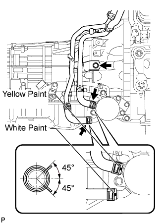 |
Connect the 2 water by-pass hoses to the transmission oil cooler and connect the water by-pass pipe with the bolt.
- Torque:
- 18 N*m{ 184 kgf*cm , 13 ft.*lbf }
- NOTICE:
- Make sure the paint marks and pinching portion of each clip are facing the directions shown in the illustration.
| 9. CONNECT WIRE HARNESS AND CONNECTOR |
Connect the park/neutral position switch connector, transmission wire connector, 2 speed sensor connectors and 3 transfer control side connectors.
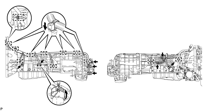
- HINT:
- Push up the lever until the claw of the transmission wire connector makes a connection sound.
Connect the harness clamp with the bolt.
- Torque:
- 8.0 N*m{ 82 kgf*cm , 71 in.*lbf }
Attach the 4 connector clamps and 8 harness clamps.
Tilt up the automatic transmission.
Connect the ground cable with the bolt.
- Torque:
- 8.4 N*m{ 85 kgf*cm , 74 in.*lbf }
| 10. INSTALL REAR NO. 1 ENGINE MOUNTING INSULATOR |
Install the rear engine mounting insulator to the transmission with the 4 bolts.
- Torque:
- 59 N*m{ 602 kgf*cm , 44 ft.*lbf }
| 11. INSTALL NO. 3 FRAME CROSSMEMBER SUB-ASSEMBLY |
Install the frame crossmember to the rear engine mounting insulator with the 4 bolts.
- Torque:
- 21 N*m{ 214 kgf*cm , 15 ft.*lbf }
Install the frame crossmember with the 4 bolts, 4 washers and 4 nuts.
- Torque:
- 110 N*m{ 1122 kgf*cm , 81 ft.*lbf }
| 12. INSTALL DRIVE PLATE AND TORQUE CONVERTER CLUTCH SETTING BOLT |
Turn the crankshaft to gain access to the installation locations of the 6 torque converter clutch setting bolts and install each bolt while holding the crankshaft pulley bolt with a wrench.
- Torque:
- 53 N*m{ 535 kgf*cm , 39 ft.*lbf }
- NOTICE:
- Install the black bolt first, and then the 5 silver bolts.
Install the flywheel housing side cover.
| 13. INSTALL STARTER ASSEMBLY |
Install the starter (Click here).
| 14. CONNECT TRANSMISSION CONTROL CABLE ASSEMBLY |
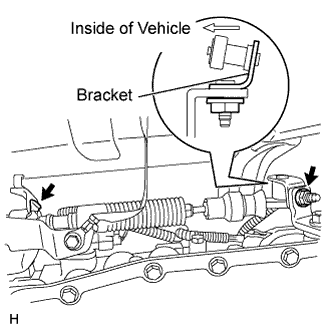 |
Connect the control cable with a new clip and the nut.
- Torque:
- 13 N*m{ 133 kgf*cm , 10 ft.*lbf }
- NOTICE:
- When connecting the cable to the transmission control shaft lever, make sure the L bracket of the cable faces the inside of the vehicle.
| 15. INSTALL FRONT EXHAUST PIPE ASSEMBLY |
for Regular Cab Standard Deck:
(Click here)
except Regular Cab Standard Deck:
(Click here)
| 16. INSTALL PROPELLER SHAFT ASSEMBLY |
| 17. INSTALL FRONT PROPELLER SHAFT ASSEMBLY |
| 18. CONNECT CABLE TO NEGATIVE BATTERY TERMINAL |
| 19. ADD AUTOMATIC TRANSMISSION FLUID |
| 20. ADD ENGINE COOLANT |
Add engine coolant.
- Standard Capacity:
Item Specified Condition w/ Trailer Towing System 13.2 liters (13.9 US qts, 11.6 Imp. qts) w/o Trailer Towing System 12.1 liters (12.8 US qts, 10.6 Imp. qts)
- NOTICE:
- Do not substitute plain water for engine coolant.
- HINT:
- TOYOTA vehicles are filled with TOYOTA SLLC at the factory. In order to avoid damage to the engine cooling system and other technical problems, only use TOYOTA SLLC or similar high quality ethylene glycol based non-silicate, non-amine, non-nitrite, non-borate coolant with long-life hybrid organic acid technology (coolant with long-life hybrid organic acid technology is a combination of low phosphates and organic acids).
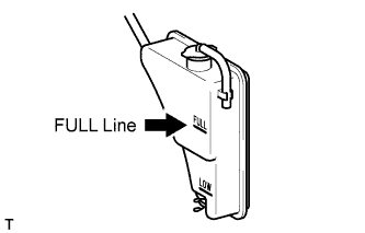
Slowly pour coolant into the radiator reservoir until it reaches the FULL line.
 |
Install the reservoir cap.
Press the inlet and outlet radiator hoses several times by hand, and then check the coolant level. If the coolant level is low, add coolant.
Install the radiator cap.
Start the engine and warm it up until the thermostat opens.
- HINT:
- The thermostat opening timing can be confirmed by pressing the radiator inlet hose by hand, and checking when the engine coolant starts to flow inside the hose.
Maintain the engine speed at 2000 to 2500 rpm.
- NOTICE:
- Make sure that the radiator reservoir still has some coolant in it.
- Pay attention to the needle of the water temperature meter. Make sure that the needle does not show an abnormally high temperature.
- If there is not enough coolant, the engine may burn out or overheat.
- Immediately after starting the engine, if the radiator reservoir does not have any coolant, perform the following: 1) stop the engine, 2) wait until the coolant has cooled down, and 3) add coolant until the coolant is filled to the FULL line.
- Run the engine at 2000 rpm until the coolant level has stabilized.
Press the inlet and outlet radiator hoses several times by hand to bleed air.
- CAUTION:
- Wear protective gloves.
- Be careful as the radiator hoses are hot.
- Keep your hands away from the fan.
Stop the engine, and wait until the engine coolant cools down to ambient temperature.
- CAUTION:
- Do not remove the radiator cap while the engine and radiator are still hot. Pressurized, hot engine coolant and steam may be released and cause serious burns.
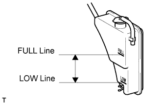
Check that the coolant level is between the FULL and LOW lines.
If the coolant level is below the LOW line, repeat all of the procedures above.
If the coolant level is above the FULL line, drain coolant so that the coolant level is between the FULL and LOW lines.
 |
| 21. INSPECT FOR ENGINE COOLANT LEAK |
 |
- CAUTION:
- Do not remove the radiator cap while the engine and radiator are still hot. Pressurized, hot engine coolant and steam may be released and cause serious burns.
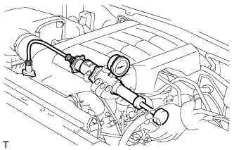
Fill the radiator with coolant and attach a radiator cap tester.
Warm up the engine.
Using the radiator cap tester, increase the pressure inside the radiator to 118 kPa (1.2 kgf/cm2, 17 psi), and check that the pressure does not drop.
If the pressure drops, check the hoses, radiator and water pump for leaks. If no external leaks are found, check the heater core, cylinder block and head.
| 22. ADJUST SHIFT LEVER POSITION (for Column Shift Type) |
Move the shift lever to N.
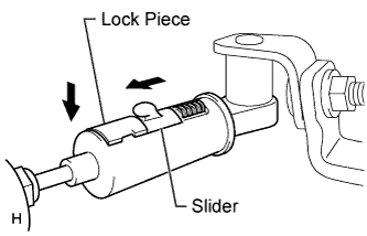
Fold back the transmission control cable adjust case cover. Then while sliding the slider toward the cable end side, press out the lock piece from the back side to release the lock.
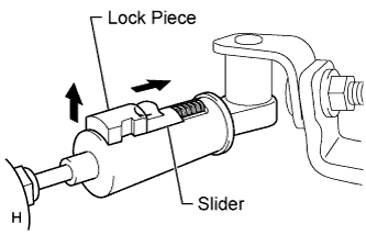 |
Check that the spring of the adjust case is applying enough tension to the shift control cable. Then press in the lock piece to set the lock.
- NOTICE:
- Use your hand to push in the lock piece. Do not use any tools.
- Securely push in the lock piece so that the protrusion of the slider is above the lock piece.
 |
Return the cover of the adjust case to its original position.
Inspect the shift lever operation after the adjustment.
| 23. ADJUST SHIFT LEVER POSITION (for Floor Shift Type) |
Move the shift lever to N.
Fold back the transmission control cable adjust case cover. Then while sliding the slider toward the cable end side, press out the lock piece from the back side to release the lock.
|
Check that the spring of the adjust case is applying enough tension to the shift control cable. Then press in the lock piece to set the lock.
- NOTICE:
- Use your hand to push in the lock piece. Do not use any tools.
- Securely push in the lock piece so that the protrusion of the slider is above the lock piece.
|
Return the cover of the adjust case to its original position.
Inspect the shift lever operation after the adjustment.
| 24. INSPECT SHIFT LEVER POSITION (for Column Shift Type) |
When moving the shift lever from N to other positions, check that the lever can be moved smoothly and accurately to each position and that the position indicator comes on in accordance with the shift lever position.
If the indicator and shift lever position do not match, carry out the following adjustment procedures.
| 25. INSPECT SHIFT LEVER POSITION (for Floor Shift Type) |
When moving the shift lever from N to other positions, check that the lever can be moved smoothly and accurately to each position and that the position indicator comes on in accordance with the shift lever position.
If the indicator and shift lever position do not match, carry out the following adjustment procedures.
| 26. CHECK FOR EXHAUST GAS LEAK |
| 27. INSTALL NO. 1 ENGINE UNDER COVER |
Hook the engine under cover to the vehicle body as shown in the illustration.
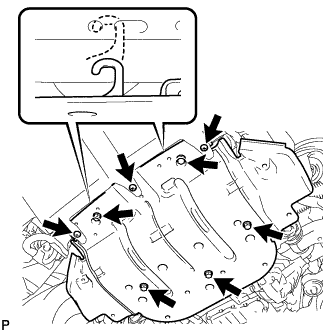 |
Install the 3 screws and 5 bolts.
- Torque:
- for bolt:
- 29 N*m{ 296 kgf*cm , 21 ft.*lbf }
- for screw:
- 3.0 N*m{ 31 kgf*cm , 27 in.*lbf }
| 28. RESET MEMORY |