DTC B2602 Key Unlock Warning Switch Circuit Malfunction |

for Preparation Click here
DESCRIPTION
A signal (ON or OFF) is sent from the main body ECU to the multiplex tilt and telescopic ECU via the CAN communication bus when the ignition key is inserted into the key cylinder. The multiplex tilt and telescopic ECU uses this signal to operate the auto away/return function.| DTC Code | Detection Condition | Trouble Area |
| B2602 | When both conditions below are met:
|
|
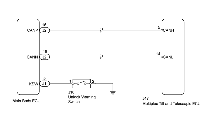
WIRING DIAGRAM
INSPECTION PROCEDURE
| 1.CHECK OTHER DTC OUTPUT |
- HINT:
- The power tilt and power telescopic steering column system uses the CAN communication system, so check its diagnostic system before proceeding to troubleshooting.
Check if the power tilt and telescopic steering column system DTC B2621 is output.
Result DTC Condition Proceed to B2621 is not output A B2621 is output B - HINT:
- If DTC B2621 is output, perform troubleshooting for B2621 first.
- DTC B2621 indicates a communication interruption for the power tilt and power telescopic steering column system.
|
| ||||
| A | |
| 2.READ VALUE USING TECHSTREAM (KEY SWITCH COMMUNICATION SIGNAL) |
Use the Data List to check if the key communication signal is functioning properly.
Tilt & Telescopic Tester Display Measurement Item/Range Normal Condition Diagnostic Note Key Switch(CAN) Communication state of unlock warning switch signal / ON or OFF ON: Communication is normal
OFF: Communication is interrupted- Result Result Proceed to "OFF" is displayed. A "ON" is displayed. B
|
| ||||
| A | |
| 3.INSPECT UNLOCK WARNING SWITCH |
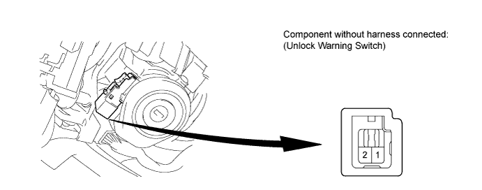
Disconnect the J18 connector from the unlock warning switch.
Measure the resistance according to the value(s) in the table below.
- Standard Resistance:
Tester Connection Switch Condition Specified Condition 1 - 2 Unlock warning switch OFF (Ignition key is removed) 10 kΩ or higher 1 - 2 Unlock warning switch ON (Ignition key is inserted) Below 1 Ω
|
| ||||
| OK | |
| 4.CHECK HARNESS AND CONNECTOR (MAIN BODY ECU - UNLOCK WARNING SWITCH) |
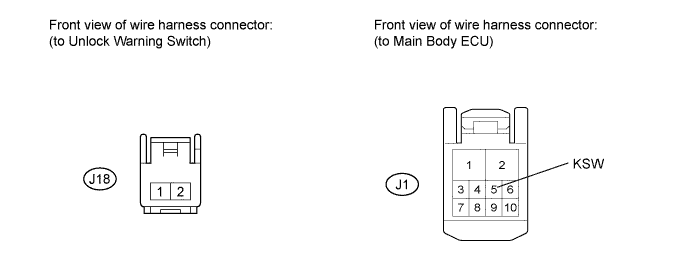
Disconnect the J1 main body ECU connector.
Measure the resistance according to the value(s) in the table below.
- Standard Resistance:
Tester Connection Condition Specified Condition J1-5 (KSW) - J18-1 Always Below 1 Ω J1-5 (KSW) - Body ground Always 10 kΩ or higher
|
| ||||
| OK | |
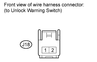
| 5.CHECK HARNESS AND CONNECTOR (UNLOCK WARNING SWITCH - BODY GROUND) |
Measure the resistance according to the value(s) in the table below.
- Standard Resistance:
Tester Connection Condition Specified Condition J18-2 - Body ground Always Below 1 Ω
 |
|
| ||||
| OK | ||
| ||