DTC P2444 Secondary Air Injection System Pump Stuck On Bank1 |
DTC P2445 Secondary Air Injection System Pump Stuck Off Bank1 |
DTC P2446 Secondary Air Injection System Pump Stuck On Bank 2 |
DTC P2447 Secondary Air Injection System Pump Stuck Off Bank 2 |

for Preparation Click here
DESCRIPTION
Refer to P2440 (Click here).| DTC Code | DTC Detection Condition | Trouble Area |
| P2444 P2446 | Secondary air pressure more than 2.4 kPa (18 mmHg) despite ECM commanding air pump to turn off (2 trip detection logic) |
|
| P2445 P2447 | Secondary air pressure less than 2.4 kPa (18 mmHg) despite ECM commanding air pump to turn on (2 trip detection logic) |
|
MONITOR DESCRIPTION
The ECM monitors the pressure in the secondary air passage using the pressure sensor located on the Air Switching Valve (ASV) of the Secondary Air Injection (AIR) system. The sensor measures the pressure in the secondary air passage and transmits a signal to the ECM.If either of the following conditions occurs, the ECM interprets it as a malfunction of the AIR system, and illuminates the MIL and sets a DTC:
- The pressure indicated by the pressure sensor does not reach threshold levels despite the ECM turning on the air pump.
- The pressure indicated by the pressure sensor exceeds threshold levels despite the ECM turning off the air pump.
MONITOR STRATEGY
| Related DTCs | P2444: Air pump stuck ON P2445: Air pump stuck OFF P2446: Air pump stuck ON P2447: Air pump stuck OFF |
| Required Sensors/Components (Main) | Pressure sensor |
| Required Sensors/Components (Related) | - |
| Frequency of Operation | Once per drive cycle |
| Duration | 7 seconds |
| MIL Operation | 2 driving cycles |
| Sequence of Operation | None |
TYPICAL ENABLING CONDITIONS
| Monitor runs whenever following DTCs not present | P0010, P0020 (VVT Oil control valve) P0011, P0021 (VVT System - Advance) P0012, P0022 (VVT System - Retard) P0013, P0023 (Exhaust VVT Oil Control Valve) P0014, P0024 (Exhaust VVT System - Advance) P0015, P0025 (Exhaust VVT System - Retard) P0016, P0018 (VVT System - Misalignment) P0017, P0019 (Exhaust VVT System - Misalignment) P0031, P0032, P0051, P0052, P101D, P103D (Air fuel ratio Sensor Heater) P0102, P0103 (Mass air flow meter) P0112, P0113 (Intake air temperature sensor) P0115, P0117, P0118 (Engine coolant temperature sensor) P0120, P0121, P0122, P0123, P0220, P0222, P0223, P2135 (Throttle position sensor) P0125 (Insufficient coolant temperature for closed loop fuel control) P0171, P0172, P0174, P0175 (Fuel system) P0301 - P0308 (Misfire) P0327, P0328, P0332, P0333, P032C, P032D, P033C, P033D (Knock sensor) P0335 (Crankshaft position sensor) P0340, P0342, P0343, P0345, P0347, P0348 (VVT sensor) P0351 - P0358 (Igniter) P0365, P0367, P0368, P0390, P0392, P0393 (Exhaust VVT sensor) P0451, P0452, P0453 (EVAP system) P0500, P0722 (Vehicle Speed Sensor) P106B (Evap. emission control system Pressure Sensor - Air Injection System Pressure Sensor correlation) P014C, P014D, P014E, P014F, P015A, P015B, P015C, P015D, P2195, P2196, P2197, P2198, P2237, P2238, P2239, P2240, P2241, P2242, P2252, P2253, P2255, P2256 (Air fuel ratio sensor) P1340 Camshaft position sensor P2431 - P2438 (Secondary air injection system pressure sensor) |
| Battery voltage | 11 V or higher |
| Atmospheric pressure | 45 kPa (337.5 mmHg) or more |
| Engine | Running |
| AIR monitor during AIR: ON*1 | Completed |
| AIR monitor during AIR: OFF*2 | Completed |
| Air injection Driver (open/short or out of range) | Not detected |
| AIR pressure sensor (open/short or out of range) | Not detected |
| Time after AIR in operation | 5 seconds or more |
| AIR pump | ON |
| AIR valve | Open |
| Engine speed | Less than 3550 rpm |
| Intake air amount | Less than 99 gm/s |
| Time after engine start | 1 second or more |
| Time after AIR in operation | 10 seconds or more |
| AIR pump | OFF |
| AIR valve | Closed |
| Engine speed | Less than 2800 rpm |
| AIR monitor during AIR: ON | Completed |
| Time after engine started | 1 seconds or more |
| Battery voltage | 11 V or higher |
| Atmospheric pressure | 45 kPa (337.5 mmHg) or more |
| Engine | Running |
| Air flow pattern check condition during AIR monitor during AIR: ON* | Completed |
| AIR injection driver fail (open/short or out of range) | Not detected |
| AIR pressure sensor fail (open/short or out of range) | Not detected |
| *: Air flow pattern check condition during AIR monitor during AIR: ON | - |
| AIR valve | Open |
| Time after secondary air injection in operation | 1 second or more |
TYPICAL MALFUNCTION THRESHOLDS
| Following conditions are met during AIR ON | - |
| Cumulative pressure pulsation | 10 kPa or higher |
| AIR pressure | 2.4 kPa or higher |
| Following conditions are met during AIR ON | - |
| Cumulative pressure pulsation | 10 kPa or higher |
| AIR pressure | Below 2.4 kPa |
| Following conditions are met during AIR ON | - |
| Cumulative pressure pulsation | Below 10 kPa |
| AIR pressure | 2.4 kPa or higher |
| Following conditions are met during AIR ON | - |
| Cumulative pressure pulsation | Below 10 kPa |
| AIR pressure | Below 2.4 kPa |
| Following conditions are met during AIR OFF | - |
| Cumulative pressure pulsation | 30 kPa or higher |
| AIR pressure | 2.4 kPa or higher |
| Following conditions are met during AIR OFF | - |
| Cumulative pressure pulsation | 30 kPa or higher |
| AIR pressure | Below 2.4 kPa |
| Following conditions are met during AIR OFF | - |
| Cumulative pressure pulsation | Below 30 kPa |
| AIR pressure | 2.4 kPa or higher |
| Following conditions are met during AIR OFF | - |
| Cumulative pressure pulsation | Below 30 kPa |
| AIR pressure | Below 2.4 kPa |
| Either condition is met: | (a) or (b) |
| (a) AIR OFF Condition 1 | Met |
| (b) AIR OFF Condition 3 | Met |
| Either condition is met: | (a) or (b) |
| (a) AIR ON Condition 2 | Met |
| (b) AIR ON Condition 4 | Met |
| Cumulative pressure pulsation | (a) or (b) |
| (a) Air flow value at Bank 1 or Bank 2 | 140 L/min or less |
| (b) Air flow value at Bank 1 and Bank 2 | 140 L/min or less |
MONITOR RESULT
Refer to Checking Monitor Status (Click here).CONFIRMATION DRIVING PATTERN
- NOTICE:
- This Air Injection Check only allows technicians to operate the AIR system for a maximum of 5 seconds.
Furthermore, the check can only be performed up to 4 times per trip. If the test is repeated, intervals of at least 30 seconds are required between checks.
While AIR system operation using the Techstream is prohibited, the Techstream display indicates the prohibition (WAIT or ERROR).
If an ERROR is displayed on the Techstream during the test, stop the engine for 10 minutes, and then try again. - Performing the Air Injection Check repeatedly may cause damage to the AIR system. If necessary, leave an interval of several minutes between System Check operations to prevent the system from overheating.
- When performing the Air Injection Check operation after the battery cable has been reconnected, wait for 7 minutes with the ignition switch turned to ON or the engine running.
- Turn the ignition switch off when the Air Injection Check operation finishes.
- Start the engine and warm it up.
- Turn the ignition switch off.
- Connect the Techstream to the DLC3.
- Turn the ignition switch to ON.
- Turn the Techstream on.
- Clear DTCs (if set) (Click here).
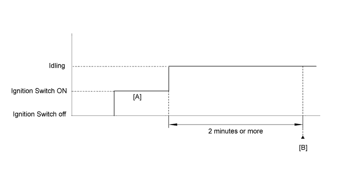
- Turn the ignition switch off and wait for at least 30 seconds.
- Turn the ignition switch to ON and turn the Techstream on [A].
- Enter the following menus: Powertrain / Engine and ECT / Utility / Air injection check / Automatic Mode.
- Start the engine after the Techstream initialization is finished.
- Perform the System Check operation by pressing ENTER (Next).
- After operating the AIR system, perform the following to confirm the AIR system pending codes: Press the ENTER (Exit).
- Check pending DTCs [B].
- OK:
- No pending DTC is output.
- After the "Air injection check" is completed, check for All Readiness by entering the following menus: Powertrain / Engine and ECT / Utility / All Readiness.
- Input the DTC: P2444, P2445, P2446 or P2447.
- Check the DTC judgment result.
Tester Display Description NORMAL - DTC judgment completed
- System normal
ABNORMAL - DTC judgment completed
- System abnormal
INCOMPLETE - DTC judgment not completed
- Perform driving pattern after confirming DTC enabling conditions
N/A - Unable to perform DTC judgment
- Number of DTCs which do not fulfill DTC preconditions has reached ECU memory limit
- HINT:
- If the judgment result shows NORMAL, the system is normal.
- If the judgment result shows ABNORMAL, the system has a malfunction.
- DTC judgment completed
- If the test result is INCOMPLETE or N/A and no pending DTC is output, perform a universal trip and check for permanent DTCs (Click here).
- HINT:
- If no permanent DTC is output, the system is normal.
- If a permanent DTC is output, the system is malfunctioning.
- Turn the ignition switch off.
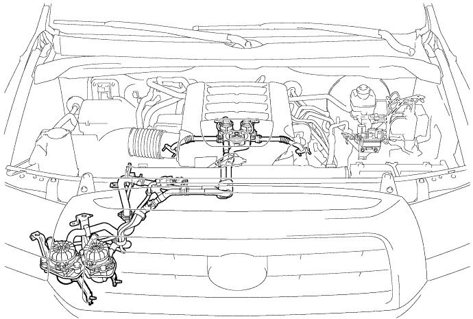
WIRING DIAGRAM
Refer to DTC P0412 (Click here).INSPECTION PROCEDURE
- HINT:
- Determination by ECM monitoring:
- The ECM locates malfunctions in the Secondary Air Injection (AIR) system by detecting the pressure in the AIR passage between the air pump and Air Switching Valve (ASV) and sets a DTC. Soon after cold engine starts, the monitor runs for a short time while the AIR system is both ON and OFF. The ECM detects both the pressure and the exhaust pulsation and compares them.
- The following 8 patterns are AIR system pressure conditions in the AIR system passage.
| Air Pump | ON |
| Air Switching Valve | Open |
| Pressure | 2.4 kPa or more |
| Pulsation Detection | Exhaust gas pulsation detected |
| Air Pump | OFF |
| Air Switching Valve | Open |
| Pressure | Less than 2.4 kPa |
| Pulsation Detection | Exhaust gas pulsation detected |
| Air Pump | ON |
| Air Switching Valve | Closed |
| Pressure | 2.4 kPa or more |
| Pulsation Detection | Exhaust gas pulsation not detected |
| Air Pump | OFF |
| Air Switching Valve | Close |
| Pressure | Less than 2.4 kPa |
| Pulsation Detection | Exhaust gas pulsation not detected |
| Air Pump | ON |
| Air Switching Valve | Open |
| Pressure | 2.4 kPa or more |
| Pulsation Detection | Exhaust gas pulsation detected |
| Air Pump | OFF |
| Air Switching Valve | Open |
| Pressure | Less than 2.4 kPa |
| Pulsation Detection | Exhaust gas pulsation detected |
| Air Pump | ON |
| Air Switching Valve | Closed |
| Pressure | 2.4 kPa or more |
| Pulsation Detection | Exhaust gas pulsation not detected |
| Air Pump | OFF |
| Air Switching Valve | Close |
| Pressure | Less than 2.4 kPa |
| Pulsation Detection | Exhaust gas pulsation not detected |
- HINT:
- The exhaust pulsation value is calculated in the ECM. If the calculated value exceeds a certain level, the ECM determines that the exhaust pulsation is in the AIR system.
- HINT:
- In case 3 and 7, as the pressure sensor detects a slight pump operation pulsation, the detected value is not constant. Since the pump outlet is blocked by closing the ASV, the average pressure is higher than in case 1 (approximately 20 to 30 kPa).
- In case 1, the average pressure is approximately 3 to 11 kPa. The value of 2.4 kPa indicated in the table above is a threshold for detecting pump malfunctions.
| Detected Conditions while AIR operating: Air pump ON, ASV Open | Detected Conditions while AIR not operating: Air pump OFF, ASV Closed | ECM Determination | DTCs Output |
| Case 1 | Case 8 | Normal | - |
| Case 1 | Case 6 | ASV stuck open | P2440 or P2442 |
| Case 1 | Case 7 | Air pump stuck ON | P2444 or P2446 |
| Case 2 | Case 8 | Air pump stuck OFF | P2445 or P2447 |
| Case 3 | Case 8 | ASV stuck closed | P2441 or P2443 |
| Case 1 | Case 5 | ASV stuck open and air pump stuck ON | P2440 and P2444 or P2442 and P2446 |
| Case 2 | Case 6 | ASV stuck open and air pump stuck OFF | P2440 and P2445 or P2442 and P2447 |
| Case 3 | Case 7 | ASV stuck closed and air pump stuck ON | P2441 and P2444 or P2443 and P2446 |
| Case 4 | Case 8 | ASV stuck closed and air pump stuck OFF | P2441 and P2445 or P2443 and P2447 |
- HINT:
- If the vacuum hose between the ASV and the pressure sensor is not connected correctly, case 4 may occur.
- By using the Techstream to perform the Air Injection Check operation in the System Check, the air-fuel ratio and the pressure in the secondary air injection system passage can be checked while the secondary air injection system is operating. This helps technicians to troubleshoot the system when it malfunctions. Furthermore, Pending Codes also can be checked by performing Utility / Air Injection Check / Automatic Mode after the repair.
- Read freeze frame data using the Techstream. Freeze frame data records the engine condition when malfunctions are detected. When troubleshooting, freeze frame data can help determine if the vehicle was moving or stationary, if the engine was warmed up or not, if the air-fuel ratio was lean or rich, and other data from the time the malfunction occurred.
- System Check:
- The pressure in the secondary air passage can be checked using the Techstream.
- Start the engine and warm it up.
- Turn the ignition switch off.
- Connect the Techstream to the DLC3.
- Turn the ignition switch to ON and turn the Techstream on.
- Enter the following menus: Powertrain / Engine and ECT / Utility / Air Injection Check / Manual Mode / AIR PUMP 1: ON, ASV1: OPEN, AIR PUMP 2: ON, ASV2: OPEN and AIR PUMP 1: OFF, ASV1 CLOSE, AIR PUMP 2: OFF, ASV2 CLOSE.
- HINT:
- When Manual Mode is selected, the Techstream initialization (atmospheric pressure measurement) is performed automatically. The initialization takes 10 seconds. After the initialization, AIR PUMP and ASV operation can be selected.
- Start the engine.
- Perform the AIR system intrusive operation while the engine is idling.
- Check that the air pump (AIR PUMP), ASV and pressure in the AIR system passage (PRESSURE) displayed on the Techstream indicate the conditions shown in the table below.
- Standard:
Operation AIR PUMP ASV PRESSURE*1 PULSATION*2 AIR PUMP: ON, ASV: OPEN ON OPEN 2.4 kPa or more 20 kPa or more AIR PUMP: OFF, ASV: CLOSE OFF CLOSE Less than 2.4 kPa Less than 30 kPa
Average pumping pressure (gauge pressure). The pressure should be 2.4 kPa or more when the AIR system operates.
*2:
The cumulative exhaust pulsation calculated by the ECM. If the calculated value exceeds a certain level, the ECM determines that the exhaust pulsation is in the AIR system. - Turn the ignition switch off.
- NOTICE:
- This Air Injection Check only allows technicians to operate the AIR system for a maximum of 5 seconds.
Furthermore, the check can only be performed up to 4 times per trip. If the test is repeated, intervals of at least 30 seconds are required between checks.
While AIR system operation using the Techstream is prohibited, the Techstream display indicates the prohibition (WAIT or ERROR).
If an ERROR is displayed on the Techstream during the test, stop the engine for 10 minutes, and then try again. - Performing the Air Injection Check repeatedly may cause damage to the AIR system. If necessary, leave an interval of several minutes between System Check operations to prevent the system from overheating.
- When performing the Air Injection Check operation after the battery cable has been reconnected, wait for 7 minutes with the ignition switch turned to ON or the engine running.
- Turn the ignition switch off when the Air Injection Check operation finishes.
- HINT:
- Bank 1 refers to the bank that includes the No. 1 cylinder*.
*: The No. 1 cylinder is the cylinder which is farthest from the transmission. - Bank 2 refers to the bank that does not include the No. 1 cylinder.
| 1.CHECK ANY OTHER DTCS OUTPUT (IN ADDITION TO DTC P2444, P2445, P2446 AND/OR P2447) |
Connect the Techstream to the DLC3.
Turn the ignition switch to ON and turn the Techstream on.
Enter the following menus: Powertrain / Engine and ECT / Trouble Codes.
Read DTCs.
If any DTCs other than P0418, P0419, P2444, P2445, P2446 and/or P2447 are output, troubleshoot those DTCs first.Result Result Proceed to P2444, P2445, P2446 and/or P2447 are output A P2444, P2445, P2446 and/or P2447 and other DTCs (except P0418 and P0419) are output B P2444, P2445, P2446 and/or P2447 and P0418 and/or P0419 are output C
|
| ||||
|
| ||||
| A | |
| 2.PERFORM ACTIVE TEST USING TECHSTREAM (ACTIVATE THE AIR PUMP HEATER) |
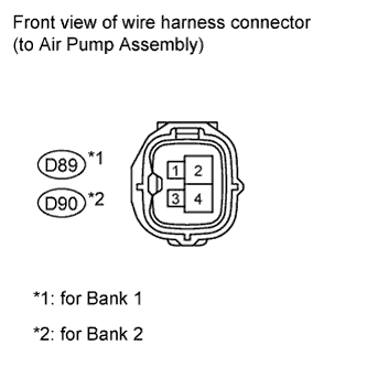
Disconnect the air pump connector.
 |
Connect the Techstream to the DLC3.
Turn the ignition switch to ON and turn the Techstream on.
Enter the following menus: Powertrain / Engine and ECT/ Active Test / Activate the Air Pump Heater.
Measure the voltage according to the value(s) in the table below.
Standard Voltage Tester Connection Condition Specified Condition D89-1 - Body ground Activate the Air Pump Heater is ON 11 to 14 V D90-1 - Body ground Activate the Air Pump Heater is ON 11 to 14 V
Reconnect the air pump connector.
|
| ||||
| OK | |
| 3.INSPECT AIR PUMP ASSEMBLY (HEATER RESISTANCE) |
Inspect the air pump assembly (Click here).
|
| ||||
| OK | |
| 4.INSPECT AIR PUMP HEATER RELAY |
Inspect the air pump heater relay (Click here).
|
| ||||
| OK | |
| 5.CHECK AIR PUMP HEATER RELAY (POWER SOURCE) |
Remove the air pump heater relay (AI HTR).
Measure the voltage according to the value(s) in the table below.
Standard Voltage Tester Connection Condition Specified Condition Air pump heater relay terminal 3 - Body ground Always 11 to 14 V
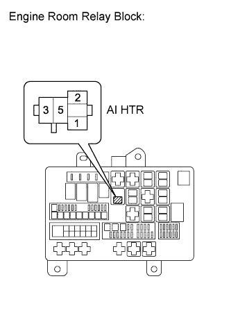 |
Reinstall the air pump heater relay (AI HTR).
|
| ||||
| OK | |
| 6.CHECK HARNESS AND CONNECTOR (AIR PUMP - AIR PUMP HEATER RELAY, BODY GROUND) |
Remove the air pump heater relay (AI HTR).
Disconnect the air pump connector.
Measure the resistance according to the value(s) in the table below.
Standard Resistance (Check for Open) Tester Connection Condition Specified Condition AI HTR relay terminal 5 - D89-1 (APH+) Always Below 1 Ω AI HTR relay terminal 5 - D90-1 (APH+) Always Below 1 Ω D89-3 (APHG) - Body ground Always Below 1 Ω D90-3 (APHG) - Body ground Always Below 1 Ω Standard Resistance (Check for Short) Tester Connection Condition Specified Condition AI HTR relay terminal 5 or D89-1 (APH+) - Body ground Always 10 kΩ or higher AI HTR relay terminal 5 or D90-1 (APH+) - Body ground Always 10 kΩ or higher
Reinstall the air pump heater relay (AI HTR).
Reconnect the air pump connector.
|
| ||||
| OK | |
| 7.PERFORM ACTIVE TEST USING TECHSTREAM (SECONDARY AIR INJECTION SYSTEM OPERATION) |
Start the engine and warm it up.
Turn the ignition switch off.
Connect the Techstream to the DLC3.
Turn the ignition switch to ON and turn the Techstream on.
Enter the following menus: Powertrain / Engine and ECT / Utility / Air Injection Check / Manual Mode / AIR PUMP 1: ON, ASV1: OPEN, AIR PUMP 2: ON, ASV2: OPEN and AIR PUMP 1: OFF, ASV1: CLOSE, AIR PUMP 2: OFF, ASV2: CLOSE.
- HINT:
- When Manual Mode is selected, the Techstream initialization (atmospheric pressure measurement) is performed automatically. The initialization takes 10 seconds. After the initialization, AIR PUMP and ASV operation can be selected.
Start the engine.
Perform the AIR system intrusive operation while the engine is idling.
Check that the air pump (AIR PUMP), ASV and pressure in the AIR system passage (PRESSURE) status displayed on the Techstream indicate the conditions shown in the table below.
- Standard:
Operation AIR PUMP ASV PRESSURE* AIR PUMP: ON, ASV: OPEN ON ON 2.4 kPa or more AIR PUMP: OFF, ASV: CLOSE OFF OFF Less than 2.4 kPa
Turn the ignition switch off.
- NOTICE:
- This Air Injection Check only allows technicians to operate the AIR system for a maximum of 5 seconds.
Furthermore, the check can only be performed up to 4 times per trip. If the test is repeated, intervals of at least 30 seconds are required between checks.
While AIR system operation using the Techstream is prohibited, the Techstream display indicates the prohibition (WAIT or ERROR).
If an ERROR is displayed on the Techstream during the test, stop the engine for 10 minutes, and then try again. - Performing the Air Injection Check repeatedly may cause damage to the AIR system. If necessary, leave an interval of several minutes between System Check operations to prevent the system from overheating.
- When performing the Air Injection Check operation after the battery cable has been reconnected, wait for 7 minutes with the ignition switch turned to ON or the engine running.
- Turn the ignition switch off when the Air Injection Check operation finishes.
|
| ||||
| OK | |
| 8.CHECK WHETHER DTC OUTPUT RECURS (DTC P2444, P2445, P2446 AND/OR P2247) |
Start the engine and warm it up.
Turn the ignition switch off.
Connect the Techstream to the DLC3.
Turn the ignition switch to ON and turn the Techstream on.
Clear DTCs (if set) (Click here).
Enter the following menus: Powertrain / Engine and ECT / Utility / Air Injection Check / Automatic Mode.
Start the engine after the Techstream initialization is finished.
Perform the System Check operation by pressing Next.
After operating the AIR system, perform the following to confirm the AIR system pending codes: Press the Exit button.
Check pending DTCs.
Turn the ignition switch off.
- NOTICE:
- When performing the Air Injection Check operation after the battery cable has been reconnected, wait for 7 minutes with the ignition switch turned to ON or the engine running.
- Turn the ignition switch off when the Air Injection Check operation finishes.
Result Result Proceed to P2444, P2445, P2446 and/or P2447 are output A No pending DTC is output B
|
| ||||
| A | |
| 9.CHECK VACUUM HOSES (PRESSURE SENSOR - AIR SWITCHING VALVE) |
Check the vacuum hose connections with the pressure sensor and ASV.
Inspect the vacuum hose for blockages and damage.
- OK:
- Vacuum hose has no blockages or damage.
|
| ||||
| OK | |
| 10.INSPECT AIR SWITCHING VALVE (PRESSURE SENSOR) |
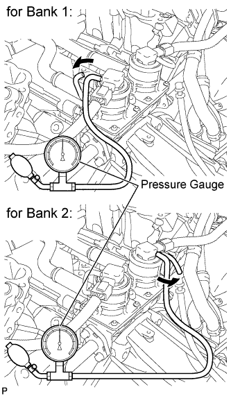 |
Connect a pressure gauge to the air pressure sensor as shown in the illustration.
Connect the Techstream to the DLC3.
Turn the ignition switch to ON and turn the Techstream on.
Enter the following menus: Powertrain / Engine and ECT / Data List / Air pump pressure (absolute) and Air Pump2 Pressure (Absolute).
Check that the pressure displayed on the Techstream fluctuates when applying the pressure to the pressure sensor with the pressure gauge.
- NOTICE:
- Do not let foreign matter enter the sensor when applying pressure.
- OK:
- Pressure fluctuates in response to pressure applied with pressure gauge.
- HINT:
- The Techstream displays the air pump pressure as absolute pressure.
|
| ||||
| OK | |
| 11.CHECK AIR INJECTION SYSTEM PIPE CONNECTIONS |
Check that all the pipes and hoses between the air pump and ASV are securely connected.
Inspect the pipes and hoses for blockages and damage.
- OK:
- AIR system piping has no blockages or damage.
|
| ||||
| OK | |
| 12.INSPECT AIR INJECTION CONTROL DRIVER (AIR INJECTION CONTROL DRIVER POWER SOURCE CIRCUIT) |
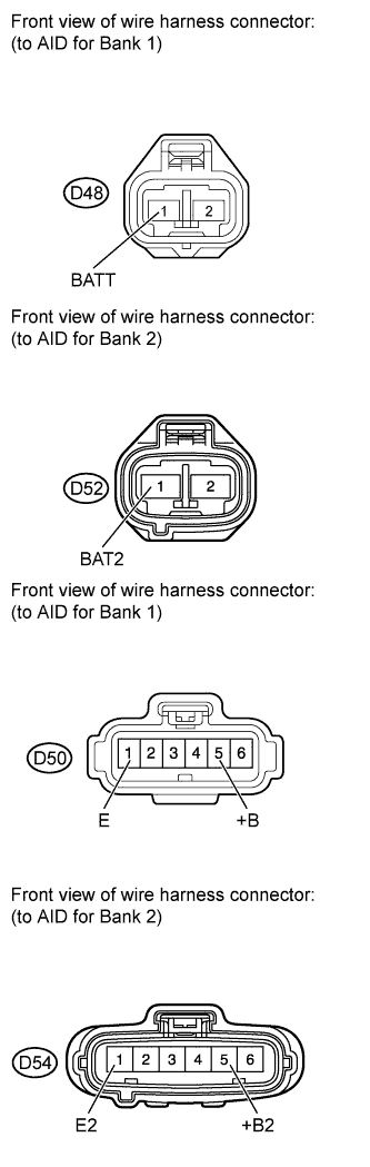 |
Disconnect the D48 and D50 or D52 and D54 AID connectors.
Measure the resistance according to the value(s) in the table below.
- Standard resistance:
Tester Connection Condition Specified Condition D50-1 (E) - Body ground Always Below 1 Ω D54-1 (E2) - Body ground Always Below 1 Ω
Turn the ignition switch to ON.
Measure the voltage according to the value(s) in the table below.
- Standard voltage:
Tester Connection Switch Condition Specified Condition D48-1 (BATT) - Body ground Always 11 to 14 V (near battery voltage) D50-5 (+B) - Body ground Ignition switch ON 11 to 14 V (near battery voltage) D52-1 (BAT2) - Body ground Always 11 to 14 V (near battery voltage) D54-5 (+B2) - Body ground Ignition switch ON 11 to 14 V (near battery voltage)
|
| ||||
| OK | |
| 13.CHECK HARNESS AND CONNECTOR (ECM - AIR INJECTION CONTROL DRIVER) |
Disconnect the D74 ECM connector.
Disconnect the D50 or D54 AID connector.
Measure the resistance according to the value(s) in the table below.
- Standard resistance:
Tester Connection Condition Specified Condition D74-54 (AIRP) - D50-4 (SIP) Always Below 1 Ω D74-53 (ARP2) - D54-4 (SIP2) Always Below 1 Ω D74-54 (AIRP) or D50-4 (SIP) - body ground Always 10 kΩ or higher D74-53 (ARP2) or D54-4 (SIP2) - body ground Always 10 kΩ or higher
|
| ||||
| OK | |
| 14.INSPECT AIR PUMP ASSEMBLY |
Start the engine and warm it up.
 |
Turn the ignition switch off.
Connect the 400 A probe of an ammeter to the positive (+) wire of the air pump.
Connect the Techstream to the DLC3.
Turn the ignition switch to ON and turn the Techstream on.
Start the engine.
Enter the following menus: Powertrain / Engine and ECT / Utility / Air Injection Check / Manual Mode / AIR PUMP 1: ON, ASV1: OPEN, AIR PUMP 2: ON, ASV2: OPEN and AIR PUMP 1: OFF, ASV1: CLOSE, AIR PUMP 2: OFF, ASV2: CLOSE.
- HINT:
- When Manual Mode is selected, the Techstream initialization (atmospheric pressure measurement) is performed automatically. The initialization takes 10 seconds. After the initialization, AIR PUMP and ASV operation can be selected.
Measure the current while the air pump is on and off.
- Standard Current:
Tester Operation Air Pump ASV Specified Condition AIR PUMP: ON, ASV: OPEN ON OPEN 10 to 40 A AIR PUMP: OFF, ASV: CLOSE OFF CLOSE Below 1 A
- NOTICE:
- This Air Injection Check only allows technicians to operate the AIR system for a maximum of 5 seconds.
Furthermore, the check can only be performed up to 4 times per trip. If the test is repeated, intervals of at least 30 seconds are required between checks.
While AIR system operation using the Techstream is prohibited, the Techstream display indicates the prohibition (WAIT or ERROR).
If ERROR is displayed on the Techstream during the test, stop the engine for 10 minutes, and then try again. - Performing the Air Injection Check repeatedly may cause damage to the AIR system. If necessary, leave an interval of several minutes between System Check operations to prevent the system from overheating.
- When performing the Air Injection Check operation after the battery cable has been reconnected, wait for 7 minutes with the ignition switch turned to ON or the engine running.
- Turn the ignition switch off when the Air Injection Check operation finishes.
|
| ||||
| OK | |
| 15.PERFORM ACTIVE TEST USING TECHSTREAM |
 |
Disconnect the AID connectors.
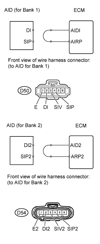
Connect terminals DI and SIV or DI2 and SIV2 of the wire harness connector for the AID.
Connect the Techstream to the DLC3.
Turn the ignition switch to ON.
Turn the Techstream on.
Enter the following menus: Powertrain / Engine and ECT / Utility / Air Injection Check / Manual Mode / AIR PUMP 1: ON, ASV 1: OPEN or AIR PUMP 2: ON, ASV 2: OPEN.
- HINT:
- When Manual Mode is selected, the Techstream initialization (atmospheric pressure measurement) is performed automatically. The initialization takes 10 seconds. After the initialization, AIR PUMP and ASV operation can be selected.
Start the engine.
Perform the AIR system forced operation while the engine is idling.
Measure the voltage between the SIV and E or SIV2 and E2 terminals of the ECM connector when the AIR system is ON and OFF.
Turn the ignition switch off.
- NOTICE:
- Performing Air Injection Check repeatedly may cause damage to the secondary air injection system. If it is necessary to repeat the check, leave an interval of several minutes between System Check operations to prevent the system from overheating.
- When performing the Air Injection Check operation after the battery cable has been reconnected, wait for 7 minutes with the ignition switch to ON or the engine running.
- Turn the ignition switch off when the Air Injection Check operation finishes.
- Standard Voltage:
Tester Connection Condition Specified Condition D50-3 (SIV) - D50-1 (E) AIR PUMP: ON, ASV: OPEN 0.5 to 2 V D54-3 (SIV2) - D54-1 (E2) AIR PUMP: ON, ASV: OPEN 0.5 to 2 V D50-3 (SIV) - D50-1 (E) AIR PUMP: OFF, ASV: CLOSE 11 to 14 V D54-3 (SIV2) - D54-1 (E2) AIR PUMP: OFF, ASV: CLOSE 11 to 14 V
Connect terminals DI and SIP or DI2 and SIP2 of the wire harness connector for the AID.
 |
Connect the Techstream to the DLC3.
Turn the ignition switch to ON.
Turn the Techstream on.
Enter the following menus: Powertrain / Engine and ECT / Utility / Air Injection Check / Manual Mode / AIR PUMP 1: ON, ASV 1: OPEN or AIR PUMP 2: ON, ASV 2: OPEN.
- HINT:
- When Manual Mode is selected, the Techstream initialization (atmospheric pressure measurement) is performed automatically. The initialization takes 10 seconds. After the initialization, AIR PUMP and ASV operation can be selected.
Start the engine.
Perform the AIR system forced operation while the engine is idling.
Measure the voltage between the SIP and E or SIP2 and E2 terminals of the ECM connector when the AIR system is ON and OFF.
Turn the ignition switch off.
- NOTICE:
- Performing Air Injection Check repeatedly may cause damage to the secondary air injection system. If it is necessary to repeat the check, leave an interval of several minutes between System Check operations to prevent the system from overheating.
- When performing the Air Injection Check operation after the battery cable has been reconnected, wait for 7 minutes with the ignition switch to ON or the engine running.
- Turn the ignition switch off when the Air Injection Check operation finishes.
- Standard Voltage:
Tester Connection Condition Specified Condition D50-4 (SIP) - D50-1 (E) AIR PUMP: ON, ASV: OPEN 0.5 to 2 V D54-4 (SIP2) - D54-1 (E2) AIR PUMP: ON, ASV: OPEN 0.5 to 2 V D50-4 (SIP) - D50-1 (E) AIR PUMP: OFF, ASV: CLOSE 11 to 14 V D54-4 (SIP2) - D54-1 (E2) AIR PUMP: OFF, ASV: CLOSE 11 to 14 V
|
| ||||
| OK | |
| 16.REPLACE AIR INJECTION CONTROL DRIVER |
Replace the air injection control driver (Click here).
| NEXT | |
| 17.CHECK WHETHER DTC OUTPUT RECURS (DTC P2444, P2445, P2446 AND/OR P2447) |
Start the engine and warm it up.
Turn the ignition switch off.
Connect the Techstream to the DLC3.
Turn the ignition switch to ON and turn the Techstream on.
Clear DTCs (if set) (Click here).
Enter the following menus: Powertrain / Engine and ECT / Utility / Air injection check / Automatic Mode.
Start the engine after the Techstream initialization is finished.
Perform the System Check operation by pressing Next.
After operating the AIR system, perform the following to confirm the AIR system pending codes: Press the Exit button.
Check pending DTCs.
Turn the ignition switch off.
- OK:
- No pending DTC is output.
- NOTICE:
- When performing the Air Injection Check operation after the battery cable has been reconnected, wait for 7 minutes with the ignition switch turned to ON or the engine running.
- Turn the ignition switch off when the Air Injection Check operation finishes.
|
| ||||
| OK | ||
| ||