AUTOMATIC TRANSMISSION UNIT > REASSEMBLY |

for Preparation Click here
| 1. BEARING POSITION |
Check the bearing positions.
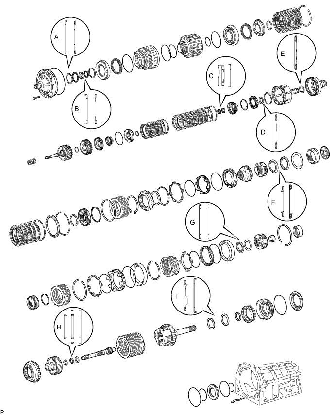
- Bearing Diameter:
Mark Front Race Diameter Inside/Outside Thrust Bearing Diameter Inside/Outside Rear Race Diameter Inside/Outside A 74.26 to 74.56 mm (2.92 to 2.94 in.)/87.39 to 87.74 mm (3.44 to 3.45 in.) 71.96 to 72.26 mm (2.83 to 2.84 in.)/85.25 to 85.60 mm (3.36 to 3.37 in.) - B 37.0 to 37.3 mm (1.46 to 1.47 in.)/52.1 to 52.3 mm (2.05 to 2.06 in.) 34.65 to 34.85 mm (81.36 to 1.37 in.)/51.56 to 51.86 mm (2.03 to 2.04 in.) - C - 21.35 to 21.60 mm (0.841 to 0.850 in.)/40.72 to 40.92 mm (1.60 to 1.61 in.) 22.65 to 22.90 mm (0.892 to 0.902 in.)/44.50 to 44.75 mm (1.75 to 1.76 in.) D - 35.65 to 35.9 mm (1.40 to 1.41 in.)/56.3 to 56.55 mm (2.22 to 2.23 in.) - E - 42.55 to 42.80 mm (1.68 to 1.69 in.)/60.84 to 61.14 mm (2.40 to 2.41 in.) - F 38.0 to 38.2 mm (1.49 to 1.50 in.)/56.50 to 57.0 mm (2.22 to 2.24 in.) 43.4 to 43.6 mm (1.71 to 1.72 in.)/58.0 to 58.25 mm (2.28 to 2.29 in.) - G - 55.76 to 55.79 mm (2.19 to 2.20 in.)/76.1 to 76.35 mm (3.00 to 3.01 in.) 53.75 to 54.0 mm (2.12 to 2.13 in.)/73.7 to 74.0 mm (2.90 to 2.91 in.) H 33.18 to 33.53 mm (1.31 to 1.32 in.)/48.8 to 49.0 mm (1.89 to 1.93 in.) 32.15 to 32.31 mm (1.26 to 1.27 in.)/48.97 to 49.77 mm (1.93 to 1.96 in.) 32.15 to 32.4 mm (1.27 to 1.28 in.)/48.7 to 49.0 mm (1.92 to 1.93 in.) I - 43.60 to 43.85 mm (1.72 to 1.73 in.)/62.95 to 63.20 mm (2.48 to 2.49 in.) 47.15 to 47.40 mm (81.86 to 1.87 in.)/67.07 to 67.40 mm (2.64 to 2.65 in.)
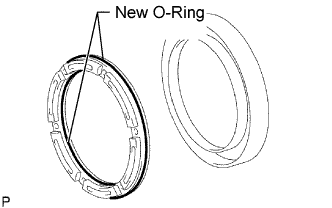
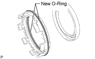
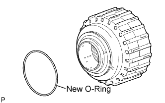
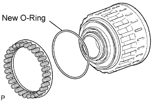
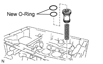
| 2. ASSEMBLE NO. 4 BRAKE PISTON AND BRAKE REACTION SLEEVE |
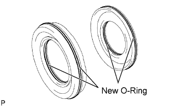 |
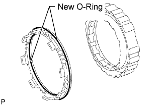
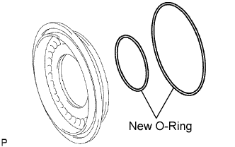
Coat 2 new O-rings with ATF, and install them to the brake reaction sleeve.
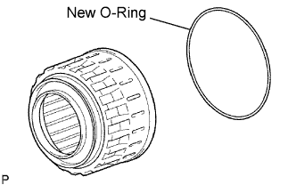
Coat 2 new O-rings with ATF, and install them to the No. 4 brake piston.
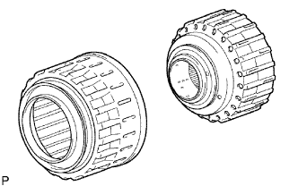
Install the No. 4 brake piston to the reaction sleeve.
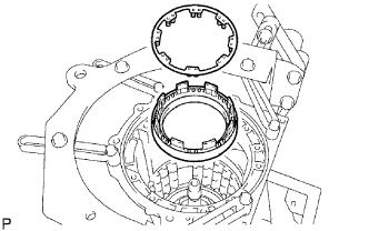
| 3. INSTALL NO. 4 BRAKE PISTON WITH BRAKE REACTION SLEEVE |
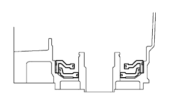 |
Install the No. 4 brake piston with brake reaction sleeve to the transmission case
- NOTICE:
- Do not damage the O-rings.
- Make sure the No. 4 brake piston is underneath the brake reaction sleeve.
| 4. INSTALL 1ST AND REVERSE BRAKE PISTON |
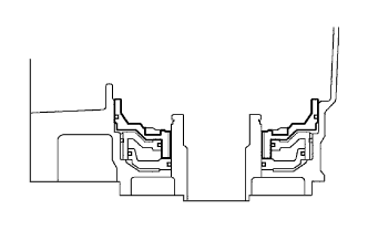 |
Coat a new O-ring with ATF.
Install the O-ring to the 1st and reverse brake piston.
With the spring seat of the piston facing upwards (the front side), install the piston to the transmission case.
- NOTICE:
- Be careful not to damage the O-ring.
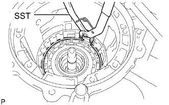
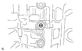
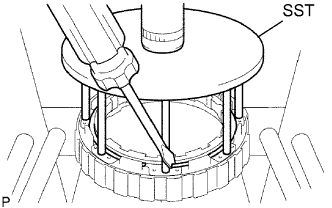
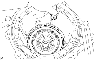
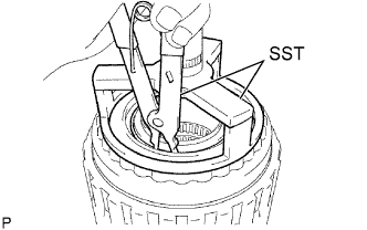
| 5. INSTALL 1ST AND REVERSE BRAKE RETURN SPRING SUB-ASSEMBLY |
 |
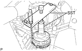
Place the brake return spring onto the 1st and reverse brake piston.
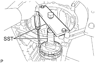
Place SST on the spring retainer, and compress the return spring.
- SST
- 09350-30020
(09350-07050)
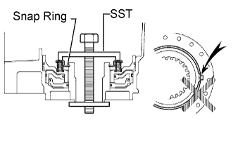 |
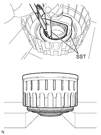
Using SST, install the snap ring.
- SST
- 09350-30020
(09350-07070)
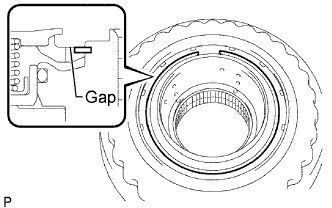
- NOTICE:
- Be sure the end gap of the snap ring is not aligned with the spring retainer claw.
Make sure the No. 4 brake piston moves smoothly when applying and releasing compressed air into and from the transmission case.
 |
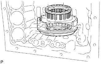
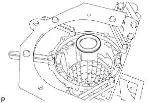
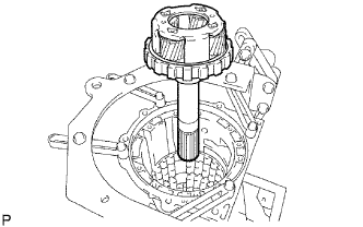
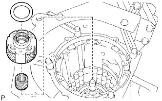
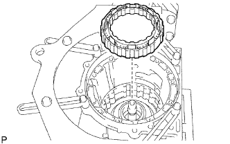
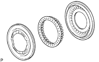
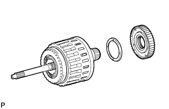
| 6. INSTALL REAR PLANETARY GEAR ASSEMBLY |
 |
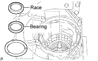
Install the thrust bearing race.
- Bearing Race Diameter:
Item Inside Outside Race I 47.15 to 47.40 mm (81.86 to 1.87 in.) 67.07 to 67.40 mm (2.64 to 2.65 in.)
Install the thrust needle roller bearing to the rear planetary gear.
- Bearing Diameter:
Item Inside Outside Bearing I 43.60 to 43.85 mm (1.72 to 1.73 in.) 62.95 to 63.20 mm (2.48 to 2.49 in.)
 |
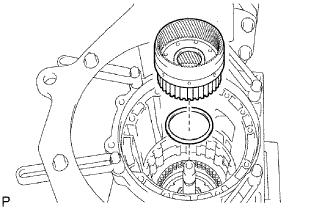
Install the rear planetary gear assembly.
 |
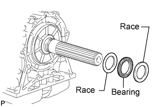
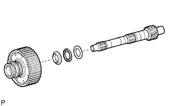
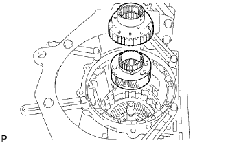
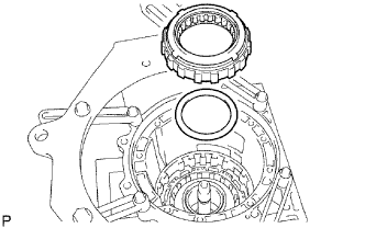
Install the rear planetary flange thrust bearing race, thrust needle roller bearing and thrust bearing race.
 |
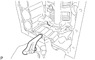
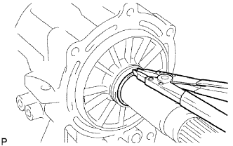
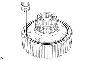
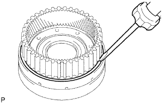
Using a snap ring expander, install the snap ring.
 |
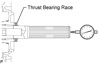
Using a dial indicator, measure the rear planetary gear end play.
- Standard end play:
- 0.02 to 0.12 mm (0.000787 to 0.00472 in.)
- HINT:
- Use the table below to select a thrust bearing race of an appropriate thickness.
- Bearing Race Thickness:
Color Thickness Brown 3.775 to 3.824 mm (0.14862 to 0.15055 in.) Brown/White 3.825 to 3.874 mm (0.15059 to 0.15252 in.) White 3.875 to 3.924 mm (0.15256 to 0.15449 in.) Orange 3.925 to 3.974 mm (0.15453 to 0.15646 in.) Orange/Black 3.975 to 4.024 mm (0.15650 to 0.15842 in.) Black 4.025 to 4.074 mm (0.15846 to 0.16039 in.) Blue 4.075 to 4.124 mm (0.16043 to 0.16236 in.) Blue/Green 4.125 to 4.174 mm (0.16240 to 0.16433 in.) Green 4.175 to 4.224 mm (0.16437 to 0.16630 in.) Brown/Yellow 4.225 to 4.274 mm (0.16634 to 0.16827 in.) Yellow 4.275 to 4.324 mm (0.16831 to 0.17024 in.) Blue/White 4.325 to 4.374 mm (0.17028 to 0.17220 in.)
 |
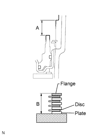
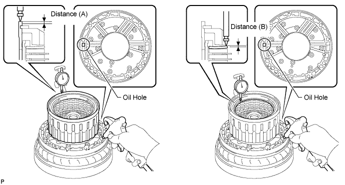
| 7. SELECT NO. 4 BRAKE FLANGE |
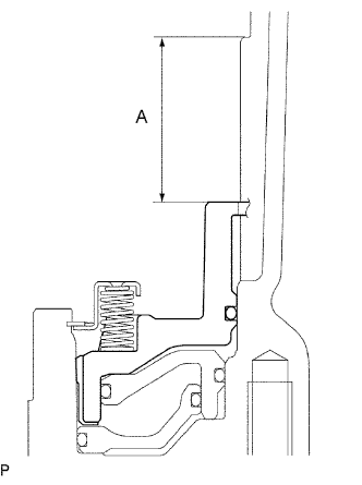
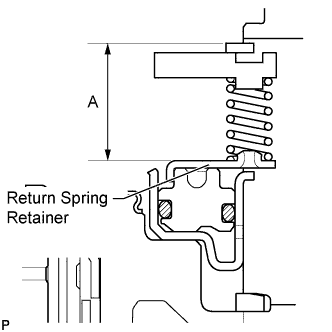
Using a vernier caliper, measure distance A (from the top surface of the 1st and reverse brake piston to the step in the transmission case) in the illustration.
- NOTICE:
- The 1st and reverse brake piston must be installed securely to the end face of the transmission case.
- HINT:
- Distance A = 36.35 to 37.09 mm (1.43 to 1.46 in.)
 |
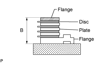
Assemble the No. 4 brake flange, 8 No. 4 brake discs and 7 No. 4 brake plates, and using a vernier caliper, measure distance B in the illustration at both ends across the diameter, and calculate the average.
- HINT:
- Distance B = 33.94 to 35.04 mm (1.34 to 1.38 in.)
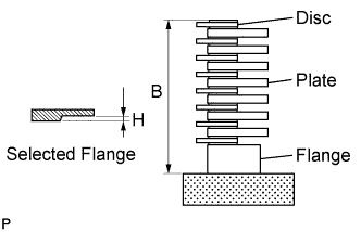 |
Select a No. 4 brake flange so that the value of measured distance A minus distance B minus thickness H is 1.35 to 1.65 mm (0.0531 to 0.0650 in.).
- Thickness H:
No. Thickness 0 0 mm (0 in.) 2 0.15 to 0.25 mm (0.00590 to 0.00984 in.) 4 0.35 to 0.45 mm (0.0138 to 0.0177 in.) 6 0.55 to 0.65 mm (0.0217 to 0.0256 in.) 8 0.75 to 0.85 mm (0.0295 to 0.0335 in.) 10 0.95 to 1.05 mm (0.0374 to 0.0413 in.) 12 1.15 to 1.25 mm (0.0453 to 0.0492 in.) 14 1.35 to 1.45 mm (0.0531 to 0.0571 in.)
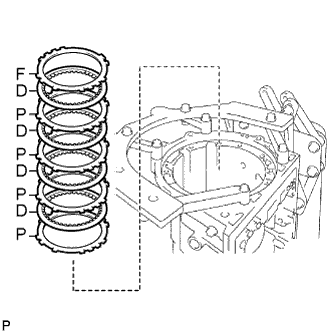
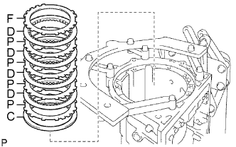
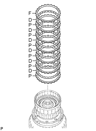
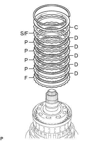
| 8. INSTALL NO. 4 BRAKE DISC |
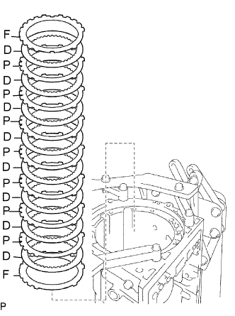 |
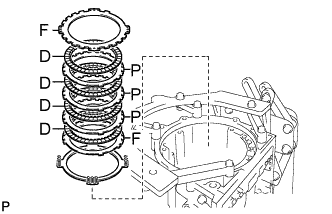
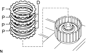
Install the flange, 8 discs, 7 plates and selected flange.
- Install in order:
- F - D - P - D - P - D - P - D - P - D - P - D - P - D - P - D - F
- HINT:
- F = Flange
- D = Disc
- P = Plate
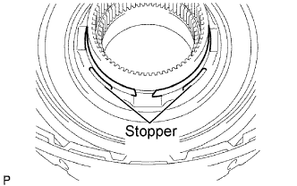
| 9. INSTALL BRAKE PLATE STOPPER SPRING |
 |
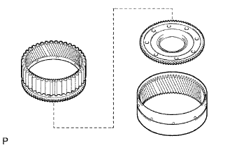
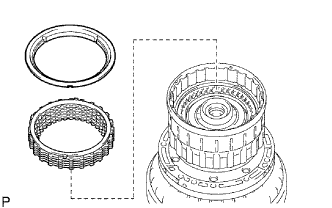
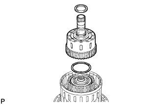
| 10. INSTALL REAR PLANETARY RING GEAR FLANGE SUB-ASSEMBLY |
 |
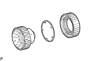
Install the rear planetary ring gear flange to the rear planetary ring gear.
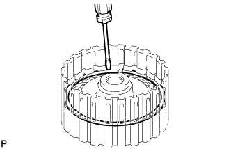
Using a screwdriver, install the snap ring.
Install the thrust bearing race, thrust needle roller bearing, thrust bearing race and planetary ring gear flange together with the rear planetary ring gear to the intermediate shaft.
- Bearing and Race Diameter:
Item Inside Outside Race H (Fr) 33.18 to 33.53 mm (1.31 to 1.32 in.) 48.8 to 49.0 mm (1.89 to 1.93 in.) Bearing H 32.15 to 32.31 mm (1.26 to 1.27 in.) 48.97 to 49.77 mm (1.93 to 1.96 in.) Race H (Rr) 32.15 to 32.4 mm (1.27 to 1.28 in.) 48.7 to 49.0 mm (1.92 to 1.93 in.)
 |
| 11. INSTALL NO. 3 1-WAY CLUTCH ASSEMBLY |
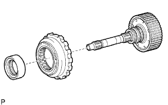 |
Install the 1-way clutch and 1-way clutch inner race to the intermediate shaft.
| 12. INSTALL INTERMEDIATE SHAFT |
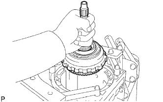 |
Install the intermediate shaft with No. 3 1-way clutch assembly to the case.
Using SST, install the snap ring.
- SST
- 09350-30020
(09350-07060)
 |
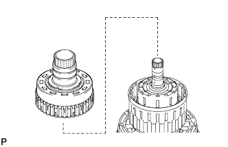
| 13. INSTALL CENTER PLANETARY GEAR ASSEMBLY |
 |
Install the planetary sun gear and center planetary gear to the case.
Coat the thrust bearing race with petroleum jelly, and install it to the center planetary gear.
- Race Diameter:
Item Inside Outside Race G 53.75 to 54.0 mm (2.12 to 2.13 in.) 73.7 to 74.0 mm (2.90 to 2.91 in.)
| 14. INSTALL NO. 2 BRAKE PISTON |
 |
Coat 2 new O-rings with ATF, and install them to the brake piston.
Press the brake piston into the brake cylinder with both hands.
- NOTICE:
- Be careful not to damage the O-rings.
Install the No. 2 brake cylinder with No. 2 brake piston to the case.
- HINT:
- Install the No. 2 brake cylinder so that the projection faces the upside of the transmission case.
Check that the oil pressure apply hole of the No. 2 brake cylinder aligns with the oil pressure apply hole of the transmission case.
 |
| 15. SELECT NO. 2 BRAKE FLANGE |
Install the No. 2 brake piston return spring and flange to the No. 2 brake piston.
Place SST on the brake flange and compress the brake return spring.
- SST
- 09351-40010
(09351-04010, 09351-04020, 09351-04040, 09351-04050)
 |
Using a screwdriver, install the snap ring to the transmission case.
Measure distance A (from the top surface of the snap ring to the surface of the brake piston return spring retainer) in the illustration.
- HINT:
- Standard distance A: 20.94 to 22.12 mm (0.824 to 0.871 in.)
 |
Remove the snap ring, flange and No. 2 brake piston return spring.
Assemble the flange, 4 discs, 3 plates and flange (thickness: 1.95 to 2.05 mm (0.0768 to 0.0807 in.)) as shown in the illustration, and using a vernier caliper, measure distance B in the illustration at both ends across the diameter, and calculate the average.
- HINT:
- Standard distance B: 18.52 to 19.15 mm (0.729 to 0.754 in.)
 |
Select a No. 2 brake flange so that the value of measured distance A minus distance B is 0.6 to 0.9 mm (0.0236 to 0.0354 in.).
- Flange Thickness:
No. Thickness 0 0 1.95 to 2.05 mm (0.0768 to 0.0807 in.) 1 2.05 to 2.15 mm (0.0807 to 0.0846 in.) 2 2.15 to 2.25 mm (0.0846 to 0.0886 in.) 3 2.25 to 2.35 mm (0.0886 to 0.0925 in.) 4 2.35 to 2.45 mm (0.0925 to 0.0965 in.) 5 2.45 to 2.55 mm (0.0965 to 0.100 in.) 6 2.55 to 2.65 mm (0.100 to 0.104 in.) 7 2.65 to 2.75 mm (0.104 to 0.108 in.)
| 16. INSTALL NO. 2 BRAKE DISC SET |
 |
Install the brake piston return spring.
Install the 2 flanges, 4 discs, 3 plates.
- Install in order:
- F - D - P - D - P - D - P - D - F
- HINT:
- D = Disc
- P = Plate
- F = Flange
Using SST and a press, compress the return spring and install the snap ring.
- SST
- 09351-40010
(09351-04010, 09351-04030, 09351-04040, 09351-04050)
|
| 17. INSTALL NO. 1 BRAKE PISTON |
 |
Coat 2 new O-rings with ATF, and install them to the brake piston.
Press the brake piston into the brake cylinder with both hands to install it.
- NOTICE:
- Be careful not to damage the O-rings.
| 18. INSTALL NO. 1 BRAKE PISTON RETURN SPRING SUB-ASSEMBLY |
 |
Install the No. 1 brake cylinder with No. 1 brake piston and the brake piston return spring to the transmission case.
Check that the oil pressure apply hole of the No. 1 brake cylinder aligns with the oil pressure apply hole of the transmission case.
 |
| 19. INSTALL NO. 1 BRAKE PISTON RETURN SPRING SNAP RING |
 |
Using SST, compress the return spring and install the No. 1 brake piston return spring snap ring.
- SST
- 09351-40010
(09351-04010, 09351-04030, 09351-04040, 09351-04050)
| 20. SELECT NO. 1 BRAKE FLANGE |
 |
Using a vernier caliper, measure distance A (from the step in the transmission case to the top surface of the No. 1 brake piston) in the illustration.
- HINT:
- Standard distance A: 19.74 to 20.22 mm (0.777 to 0.796 in.)
Assemble the 4 plates, 4 discs and flange (thickness: 2.15 to 2.25 mm (0.0846 to 0.0886 in.)) as shown in the illustration, and using a vernier caliper, measure distance B in the illustration at both ends across the diameter, and calculate the average.
- HINT:
- Standard distance B: 18.93 to 19.39 mm (0.745 to 0.763 in.)
Select a No. 1 brake flange so that the value of measured distance A minus distance B is 0.56 to 0.86 mm (0.0220 to 0.0339 in.).
- Flange Thickness:
No. Thickness 0 1.95 to 2.05 mm (0.0768 to 0.0807 in.) 1 2.15 to 2.25 mm (0.0846 to 0.0886 in.) 2 2.35 to 2.45 mm (0.0925 to 0.0965 in.) 3 2.55 to 2.65 mm (0.100 to 0.104 in.)
| 21. INSTALL NO. 1 BRAKE DISC |
 |
Install the 4 plates, 4 discs and flange.
- Install in order:
- P - D - P - D - P - D - P - D - F
- HINT:
- P = Plate
- D = Disc
- F = Flange
| 22. INSTALL CENTER PLANETARY RING GEAR |
 |
Install the center planetary ring gear and front planetary ring gear flange to the front planetary ring gear.
Using a screwdriver, install the snap ring.
 |
| 23. INSTALL FRONT PLANETARY RING GEAR |
 |
Install the thrust needle roller bearing and front planetary ring gear to the case.
- Thrust Needle Roller Bearing Diameter:
Item Inside Outside Bearing G 55.76 to 55.79 mm (2.19 to 2.20 in.) 76.1 to 76.35 mm (3.00 to 3.01 in.)
| 24. INSTALL FRONT PLANETARY GEAR ASSEMBLY |
 |
Install the thrust washer and thrust needle roller bearing.
Coat the thrust bearing race with petroleum jelly, and install it to the front planetary ring gear.
- Thrust Needle Roller Bearing and Race Diameter:
Item Inside Outside Bearing F 43.4 to 43.6 mm (1.71 to 1.72 in.) 58.0 to 58.25 mm (2.28 to 2.29 in.) Race F 38.0 to 38.2 mm (1.49 to 1.50 in.) 56.50 to 57.0 mm (2.22 to 2.24 in.)
Install the front planetary gear assembly and 1-way clutch inner race to the case.
 |
| 25. INSTALL NO. 3 BRAKE PISTON |
 |
Coat 2 new O-rings with ATF, and install them to the No. 3 brake piston.
Press the No. 3 brake cylinder into the No. 3 brake piston with both hands to install it.
- NOTICE:
- Be careful not to damage the O-rings.
Using SST and a press, compress the return spring and install the snap ring.
- SST
- 09351-40010
- NOTICE:
- Be sure the end gap of the snap ring is not aligned with the spring retainer claw.
 |
| 26. INSTALL NO. 3 BRAKE CYLINDER |
 |
Install the No. 3 brake cylinder to the case.
| 27. INSTALL 1-WAY CLUTCH ASSEMBLY |
 |
Install the thrust washer and 1-way clutch to the case.
| 28. INSTALL NO. 3 BRAKE PISTON HOLE SNAP RING |
|
Using SST, install the snap ring.
- SST
- 09350-30020
(09350-07060)
| 29. INSTALL NO. 3 BRAKE DISC |
 |
Install the cushion plate, 4 plates, 4 discs and flange to the case.
- Install in order:
- C - P - D - P - D - P - D - P - D - F
- HINT:
- C = Cushion plate
- P = Plate
- D = Disc
- F = Flange
| 30. INSTALL NO. 3 BRAKE SNAP RING |
 |
Using a screwdriver, install the snap ring.
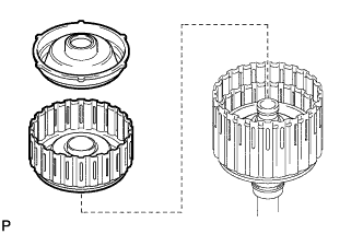
| 31. INSTALL DIRECT CLUTCH PISTON SUB-ASSEMBLY |
 |
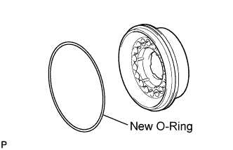
Coat 2 new O-rings with ATF, and install them in the direct clutch piston.
Install the direct clutch return spring and No. 2 clutch balancer to the direct clutch piston sub-assembly.
 |
Press the direct clutch piston with clutch return spring and clutch balancer into the reverse clutch piston with both hands to install them.
- NOTICE:
- Be careful not to damage the O-ring.
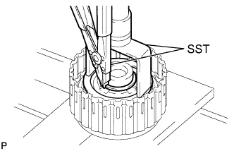
Place SST on the direct clutch balancer, and compress the return spring with a press.
- SST
- 09320-89010
- SST
- 09350-30020
- NOTICE:
- Stop pressing when the spring sheet is lowered to a position 1 to 2 mm (0.0394 to 0.0787 in.) from the snap ring groove to prevent the spring sheet from being deformed.
 |
Using SST, install the snap ring.
- SST
- 09350-30020
(09350-07070)
- NOTICE:
- Do not expand the snap ring excessively.
 |
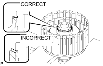
Position the end gap of the snap ring in the balancer as shown in the illustration.
- NOTICE:
- Be sure the end gap of the snap ring is not aligned with the spring retainer claw.
| 32. INSTALL REVERSE CLUTCH PISTON SUB-ASSEMBLY |
 |
Coat a new O-ring with ATF, and install it to the clutch drum.
Coat a new O-ring with ATF, and install it to the reverse clutch piston.
 |
Press the clutch drum into the reverse clutch piston with both hands.
- NOTICE:
- Be careful not to damage the O-rings.
 |
| 33. INSTALL NO. 3 CLUTCH BALANCER |
 |
Coat a new O-ring with ATF, and install it to the reverse clutch piston.
Install the reverse clutch return spring and balancer to the reverse clutch piston.
Place SST on the clutch balancer, and compress the return spring with a press.
- SST
- 09387-00070
- NOTICE:
- Stop pressing when the spring sheet is lowered to a position 1 to 2 mm (0.0394 to 0.0787 in.) from the snap ring groove to prevent the spring sheet from being deformed.
 |
Using SST, install the snap ring.
- SST
- 09350-30020
(09350-07070)
- NOTICE:
- Do not expand the snap ring excessively.
Position the end gap of the snap ring in the piston as shown in the illustration.
- NOTICE:
- Be sure the end gap of the snap ring is not aligned with the spring retainer claw.
 |
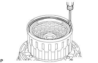
| 34. INSTALL DIRECT CLUTCH DISC |
 |
Install the 6 plates, 6 discs and direct clutch flange to the clutch drum.
- Install in order:
- P - D - P - D - P - D - P - D - P - D - P - D - F
- HINT:
- P = Plate
- D = Disc
- F = Flange
- NOTICE:
- Before assembling new discs, soak them in ATF for at least 2 hours.
Using a screwdriver, install the snap ring to the clutch drum.
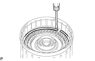 |
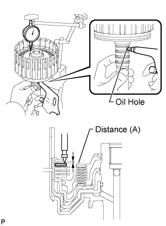
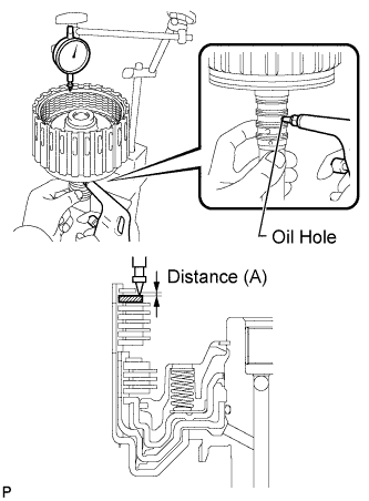
Using a dial indicator, measure the moving distance (A) of the clutch flange at both ends across the diameter while applying compressed air (392 kPa, 4.0 kgf/cm2, 57 psi) into the oil hole as shown in the illustration.
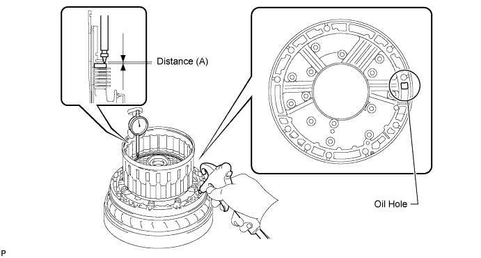
- Standard moving distance (A):
- 0.60 to 0.90 mm (0.0236 to 0.0354 in.)
- Flange Thickness:
Mark Thickness 2 2.95 to 3.05 mm (0.116 to 0.120 in.) 3 3.05 to 3.15 mm (0.120 to 0.124 in.) 4 3.15 to 3.25 mm (0.124 to 0.128 in.) 5 3.25 to 3.35 mm (0.128 to 0.132 in.) 6 3.35 to 3.45 mm (0.132 to 0.136 in.) 7 3.45 to 3.55 mm (0.136 to 0.140 in.) 8 3.55 to 3.65 mm (0.140 to 0.144 in.) 9 3.65 to 3.75 mm (0.144 to 0.148 in.) A 3.75 to 3.85 mm (0.148 to 0.152 in.)
Temporarily remove the snap ring, replace the flange with the selected flange and reinstall the snap ring.
| 35. SELECT REVERSE CLUTCH FLANGE |
 |
Using a screwdriver, install the snap ring to the clutch drum.
- NOTICE:
- Make sure to install the direct clutch and reverse clutch snap rings so that their openings face opposite directions.
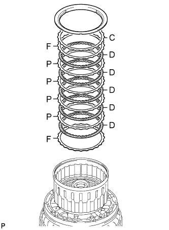
Install the 2 flanges, 5 discs, 4 plates, cushion plate and reverse clutch reaction sleeve to the clutch drum.
- Install in order:
- F - D - P - D - P - D - P - D - P - D - F - C
- HINT:
- F = Flange
- D = Disc
- P = Plate
- C = Cushion plate
 |
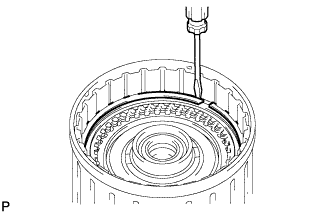
Using a screwdriver, install the hole snap ring.
 |
Using a dial indicator, measure the moving distance (A minus B) of the top surface of the reverse clutch piston (A) and cushion plate at both ends across the diameter (B) while applying compressed air (392 kPa, 4.0 kgf/ cm2, 57 psi) into the oil hole as shown in the illustration. Then choose a flange of an appropriate thickness from the table so that the measured value is within the standard range.
- Standard moving distance (A minus B):
- 0.50 to 0.80 mm (0.0197 to 0.0315 in.)
- Flange Thickness:
Mark Thickness 0 2.75 to 2.85 mm (0.108 to 0.112 in.) 1 2.85 to 2.95 mm (0.112 to 0.116 in.) 2 2.95 to 3.05 mm (0.116 to 0.120 in.) 3 3.05 to 3.15 mm (0.120 to 0.124 in.) 4 3.15 to 3.25 mm (0.124 to 0.128 in.) 5 3.25 to 3.35 mm (0.128 to 0.132 in.) 6 3.35 to 3.45 mm (0.132 to 0.136 in.) 7 3.45 to 3.55 mm (0.136 to 0.140 in.) 8 3.55 to 3.65 mm (0.140 to 0.144 in.) 9 3.65 to 3.75 mm (0.144 to 0.148 in.) A 3.75 to 3.85 mm (0.148 to 0.152 in.)
Remove the snap ring, reverse clutch reaction sleeve and rear clutch disc set from the clutch drum.
 |
| 36. INSTALL FORWARD CLUTCH PISTON SUB-ASSEMBLY AND COAST CLUTCH PISTON |
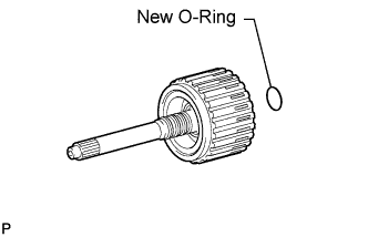 |
Coat a new O-ring with ATF, and install it to the input shaft.
Install the forward clutch piston and coast clutch piston to the input shaft.
 |
Coat a new O-ring with ATF, and install it to the No. 1 clutch balancer.
 |
Install the forward clutch return spring and No. 1 clutch balancer to the input shaft.
- NOTICE:
- Be careful not to damage the O-rings.
Place SST on the No. 1 clutch balancer, and compress the return spring with a press.
- SST
- 09350-30020
(09350-07040)
- NOTICE:
- Stop pressing when the spring sheet is lowered to a position 1 to 2 mm (0.0394 to 0.0787 in.) from the snap ring groove to prevent the spring sheet from being deformed.
 |
Using SST, install the snap ring.
- SST
- 09350-30020
(09350-07070)
- NOTICE:
- Do not expand the snap ring excessively.
Position the end gap of the snap ring in the balancer as shown in the illustration.
- NOTICE:
- Be sure the end gap of the snap ring is not aligned with the spring retainer claw.
 |
| 37. INSTALL COAST CLUTCH DISC SET |
 |
Install the 3 plates, 3 discs and flange.
- Install in order:
- P - D - P - D - P - D - F
- HINT:
- P = Plate
- D = Disc
- F = Flange
- NOTICE:
- Before assembling new discs, soak them in ATF for at least 2 hours.
Temporarily install the snap ring.
 |
Using a dial indicator, measure the moving distance (A) of the clutch flange at both ends across the diameter while applying compressed air (196 kPa, 2.0 kgf/cm2, 28 psi) into the oil hole as shown in the illustration.
- Standard moving distance (A):
- 0.30 to 0.60 mm (0.0118 to 0.0236 in.)
- Flange Thickness:
Mark Thickness 0 2.95 to 3.05 mm (0.116 to 0.120 in.) 1 3.05 to 3.15 mm (0.120 to 0.124 in.) 2 3.15 to 3.25 mm (0.124 to 0.128 in.) 3 3.25 to 3.35 mm (0.128 to 0.132 in.) 4 3.35 to 3.45 mm (0.132 to 0.136 in.) 5 3.45 to 3.55 mm (0.136 to 0.140 in.) 6 3.55 to 3.65 mm (0.140 to 0.144 in.) 7 3.65 to 3.75 mm (0.144 to 0.148 in.) 8 3.75 to 3.85 mm (0.148 to 0.152 in.) A 3.85 to 3.95 mm (0.152 to 0.156 in.)
 |
Temporarily remove the snap ring, replace the flange with the selected flange and reinstall the snap ring.
| 38. INSTALL UNDERDRIVE 1-WAY CLUTCH ASSEMBLY |
 |
Install the No. 2 clutch hub thrust washer to the coast clutch hub.
- HINT:
- Use a small amount of MP grease to make the thrust washer stay securely in place.
Install the 1-way clutch to the coast clutch hub.
| 39. INSPECT UNDERDRIVE 1-WAY CLUTCH ASSEMBLY |
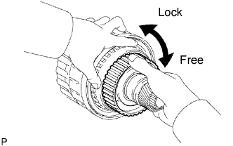 |
Hold the reverse clutch hub and turn the 1-way clutch assembly.
Check that the 1-way clutch turns freely clockwise and locks when turned counterclockwise.
If there is a problem with the 1- way clutch, replace the No. 2 1-way clutch assembly.
| 40. INSTALL COAST CLUTCH HUB SUB-ASSEMBLY WITH UNDERDRIVE 1-WAY CLUTCH ASSEMBLY |
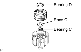 |
Install the 2 thrust needle roller bearings, thrust bearing race and coast clutch hub with the underdrive 1- way clutch to the input shaft.
- HINT:
- Use a small amount of MP grease to make the thrust needle roller bearings and race stay securely in place.
- Bearing and Race Diameter:
Item Inside Outside Bearing C 21.35 to 21.60 mm (0.841 to 0.850 in.) 40.72 to 40.92 mm (1.60 to 1.61 in.) Race C 22.65 to 22.90 mm (0.892 to 0.902 in.) 44.50 to 44.75 mm (1.75 to 1.76 in.) Bearing D 35.65 to 35.9 mm (1.40 to 1.41 in.) 56.3 to 56.55 mm (2.22 to 2.23 in.)
| 41. INSTALL FORWARD MULTIPLE DISC CLUTCH DISC SET |
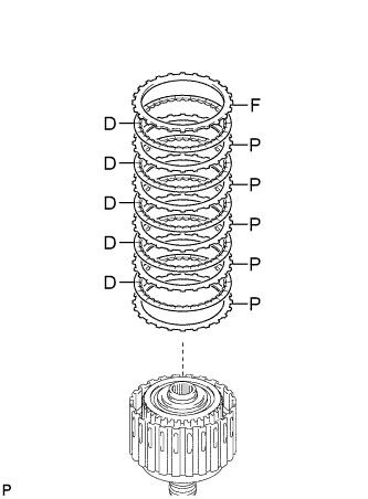 |
Install the 5 plates, 5 discs and flange to the input shaft.
- Install in order:
- P - D - P - D - P - D - P - D - P - D - F
- HINT:
- P = Plate
- D = Disc
- F = Flange
- NOTICE:
- Before assembling new discs, soak them in ATF for at least 2 hours.
Temporarily install the snap ring.
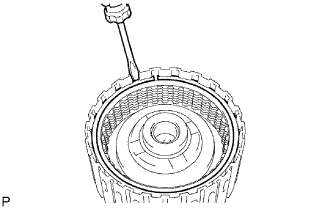 |
Using a dial indicator, measure the moving distance (A) of the clutch flange at both ends across the diameter while applying compressed air (196 kPa, 2.0 kgf/cm2, 28 psi) into the oil hole as shown in the illustration.
- Standard moving distance (A):
- 0.7 to 1.0 mm (0.0276 to 0.0394 in.)
- Flange Thickness:
Mark Thickness 0 2.95 to 3.05 mm (0.116 to 0.120 in.) 1 3.05 to 3.15 mm (0.120 to 0.124 in.) 2 3.15 to 3.25 mm (0.124 to 0.128 in.) 3 3.25 to 3.35 mm (0.128 to 0.132 in.) 4 3.35 to 3.45 mm (0.132 to 0.136 in.) 5 3.45 to 3.55 mm (0.136 to 0.140 in.) 6 3.55 to 3.65 mm (0.140 to 0.144 in.) 7 3.65 to 3.75 mm (0.144 to 0.148 in.) 8 3.75 to 3.85 mm (0.148 to 0.152 in.) 9 3.85 to 3.95 mm (0.152 to 0.156 in.) A 3.95 to 4.05 mm (0.156 to 0.159 in.)
 |
Temporarily remove the snap ring, replace the flange with the selected flange and reinstall the snap ring.
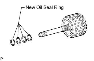
| 42. INSTALL INPUT SHAFT OIL SEAL RING |
Coat 4 new oil seal rings with ATF.
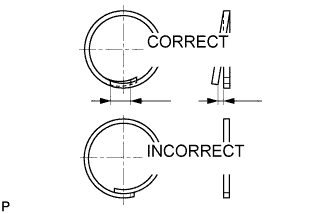
Overlap the seal ring ends in the axial direction.
- NOTICE:
- Overlapping the seal ring ends in the axial direction prevents damage to the seal ring.
- Do not overlap the seal ring ends in the radial direction, as this may damage the seal ring.
 |
Squeeze the ends of the 4 oil seal rings together, and then install them to the input shaft groove.
- NOTICE:
- Do not excessively widen the rings.
- HINT:
- After installing the oil seal rings, check that they rotate smoothly.
 |
| 43. INSTALL INPUT SHAFT ASSEMBLY |
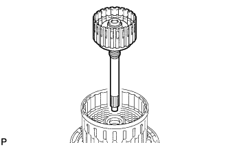 |
Install the input shaft to the clutch drum.
| 44. INSTALL FORWARD CLUTCH HUB SUB-ASSEMBLY |
 |
Install the No. 3 clutch hub thrust washer, forward clutch hub and thrust needle roller bearing to the clutch drum.
- NOTICE:
- Before installing the forward clutch hub, apply ATF to the forward clutch hub bush sliding surfaces. After the installation, check that the forward clutch hub rotates smoothly.
- HINT:
- Use a small amount of MP grease to make the thrust needle roller bearing and thrust washer stay securely in place.
- Bearing Diameter:
Item Inside Outside Bearing E 42.55 to 42.80 mm (1.68 to 1.69 in.) 60.84 to 61.14 mm (2.40 to 2.41 in.)
| 45. INSTALL REVERSE CLUTCH HUB SUB-ASSEMBLY |
 |
Install the reverse clutch hub to the clutch drum.
- NOTICE:
- Before installing the reverse clutch hub, apply ATF to the reverse clutch hub bush sliding surfaces. After the installation, check that the reverse clutch rotates smoothly.
| 46. INSTALL REAR CLUTCH DISC SET |
 |
Install the flange, 5 discs, 4 plates, selected flange, cushion plate and reverse clutch reaction sleeve to the clutch drum.
- Install in order:
- F - D - P - D - P - D - P - D - P - D - S/F - C
- HINT:
- F = Flange
- D = Disc
- P = Plate
- S/F = Selected flange
- C = Cushion plate
Using a screwdriver, install the snap ring to the clutch drum.
| 47. INSTALL NO. 2 1-WAY CLUTCH ASSEMBLY |
 |
Install the clutch drum thrust washer to the clutch drum.
- HINT:
- Use a small amount of MP grease to make the thrust washer stay securely in place.
Install the 1-way clutch to the clutch drum.
| 48. INSPECT NO. 2 1-WAY CLUTCH ASSEMBLY |
|
Hold the reverse clutch hub and turn the 1-way clutch assembly.
Check that the 1-way clutch turns freely clockwise and locks when turned counterclockwise.
If there is a problem with the 1- way clutch, replace the No. 2 1-way clutch assembly.
| 49. INSTALL CLUTCH DRUM AND INPUT SHAFT ASSEMBLY |
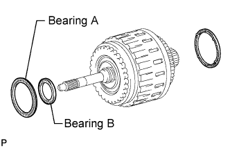 |
Install the 2 thrust needle roller bearings.
- HINT:
- Use a small amount of MP grease to make the thrust needle roller bearings stay securely in place.
- Bearing Diameter:
Item Inside Outside Bearing A 71.96 to 72.26 mm (2.83 to 2.84 in.) 85.25 to 85.6 mm (3.36 to 3.37 in.) Bearing B 34.65 to 34.85 mm (81.36 to 1.37 in.) 51.56 to 51.86 mm (2.03 to 2.04 in.)
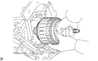
Coat the clutch drum thrust washer with petroleum jelly and install it to the clutch drum and input shaft assembly.
Install the clutch drum and input shaft assembly to the transmission case.
 |
| 50. INSTALL OIL PUMP ASSEMBLY |
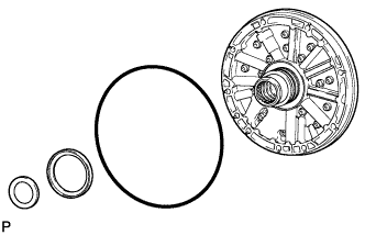 |
Coat a new O-ring with ATF, and install it to the oil pump.
Install the 2 thrust bearing races to the front oil pump.
- Thrust Bearing Race Diameter:
Item Inside Outside Race A 74.26 to 74.56 mm (2.92 to 2.94 in.) 87.39 to 87.74 mm (3.44 to 3.45 in.) Race B 37.0 to 37.3 mm (1.46 to 1.47 in.) 52.1 to 52.3 mm (2.05 to 2.06 in.)
Pass the input shaft through the center hole of the oil pump, and align the bolt holes of the oil pump assembly with the transmission case.
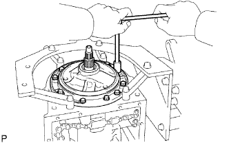 |
Hold the input shaft, and lightly press the oil pump body to slide the oil seal rings into the overdrive direct clutch drum.
Apply seal packing to the flanges of the bolts.
- Seal packing:
- Toyota Genuine Seal Packing 1281,
Three Bond 1281 or equivalent
Install the oil pump with the 10 bolts.
- Torque:
- 21 N*m{ 215 kgf*cm , 16 ft.*lbf }
- NOTICE:
- During installation, do not allow oil to contact the bolts or the surface of the oil pump body.
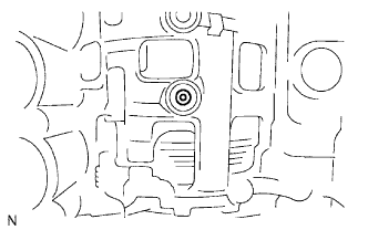
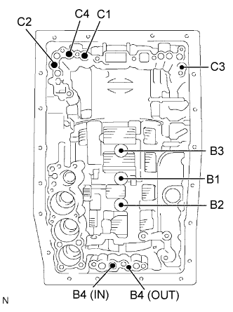
| 51. INSPECT INDIVIDUAL PISTON OPERATION |
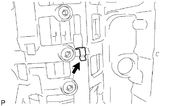
Check the operating sound while applying compressed air into the oil holes indicated in the illustration.
- HINT:
- When inspecting the rear clutch, check the operating sound with the C3 accumulator piston hole closed.
- If there is no sound, disassemble and check the installation condition of the parts.
- Forward multiple disc clutch (C1)
- Direct clutch (C2)
- Rear clutch (C3)
- Coast clutch (C4)
- No. 1 brake (B1)
- No. 2 brake (B2)
- No. 3 brake (B3)
- No. 4 brake (B4)
 |
| 52. INSTALL MANUAL VALVE LEVER SHAFT OIL SEAL |
 |
Using SST, tap in 2 new oil seals.
- SST
- 09350-30020
(09350-07110)
- Standard depth:
- -0.3 to 0.3 mm (-0.0118 to 0.0118 in.)
Coat the lips of the oil seals with MP grease.
| 53. INSTALL MANUAL VALVE LEVER SUB-ASSEMBLY |
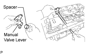 |
Install a new spacer to the manual valve lever.
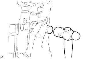
Push the manual valve lever shaft through the transmission case, and install the manual valve lever to the shaft.
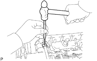
Using a hammer, tap in a new spring pin.
 |
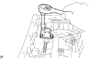
Align the manual valve lever indentation with the spacer hole, and stake them together with the punch.
 |
Check that the shaft rotates smoothly.
| 54. INSTALL PARKING LOCK PAWL SHAFT |
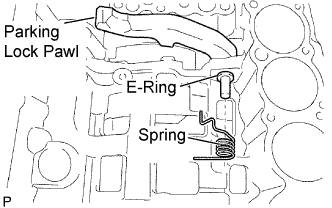 |
Install a new E-ring to the shaft.
Install the parking lock pawl, shaft and spring.
| 55. INSTALL PARKING LOCK ROD SUB-ASSEMBLY |
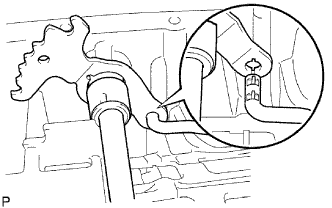 |
Connect the parking lock rod to the manual valve lever.
| 56. INSTALL PARKING LOCK PAWL BRACKET |
 |
Install the parking lock pawl bracket to the transmission case with the 3 bolts.
- Torque:
- 7.4 N*m{ 75 kgf*cm , 65 in.*lbf }
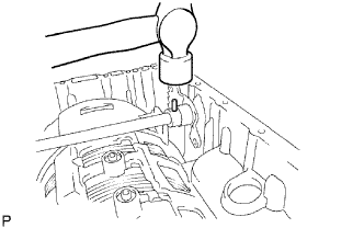
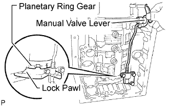
Move the manual valve lever to the P position, and confirm that the planetary ring gear is correctly locked by the lock pawl.
 |
| 57. INSTALL B-1 ACCUMULATOR VALVE |
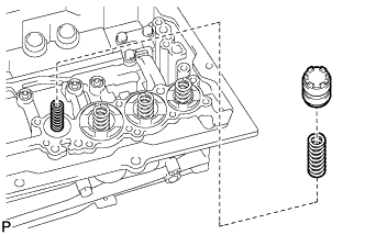 |
Install the 2 springs and accumulator valve to the hole.
- Spring Diameter:
Spring Free Length
Outer DiameterColor B-1 Inner 44.98 mm (1.77 in.)
11.3 mm (0.445 in.)Natural B-1 Outer 46.36 mm (1.83 in.)
17.1 mm (0.673 in.)Natural
| 58. INSTALL C-3 ACCUMULATOR PISTON |
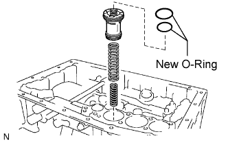 |
Coat 2 new O-rings with ATF, and install them to the piston.
Install the 2 springs and accumulator piston to the hole.
- Spring Diameter:
Spring Free Length
Outer DiameterColor C-3 Inner 44.0 mm (1.73 in.)
14.0 mm (0.551 in.)Yellow C-3 Outer 73.35 mm (2.89 in.)
19.9 mm (0.783 in.)Red
| 59. INSTALL B-3 ACCUMULATOR PISTON |
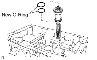 |
Coat 2 new O-rings with ATF, and install them to the piston.
Install the spring and accumulator piston to the hole.
- Spring Diameter:
Spring Free Length
Outer DiameterColor B-3 70.5 mm (2.78 in.)
19.7 mm (0.776 in.)Purple
| 60. INSTALL C-2 ACCUMULATOR PISTON |
 |
Coat 2 new O-rings with ATF, and install them to the piston.
Install the spring and accumulator piston to the hole.
- Spring Diameter:
Spring Free Length
Outer DiameterColor C-2 62.0 mm (2.44 in.)
15.9 mm (0.626 in.)White
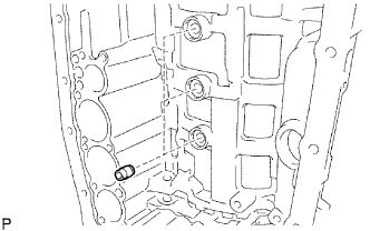
| 61. INSTALL CHECK BALL BODY |
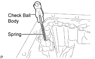 |
Install the spring and check ball body.
| 62. INSTALL BRAKE DRUM GASKET |
 |
Install 3 new brake drum gaskets.
| 63. INSTALL TRANSMISSION CASE GASKET |
 |
Install 3 new transmission case gaskets.
| 64. INSTALL TRANSMISSION VALVE BODY ASSEMBLY |
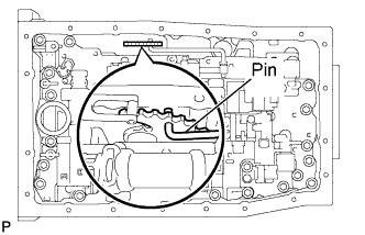 |
Align the hole of the manual valve with the pin of the lever and connect the pin to the manual valve.
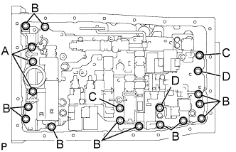
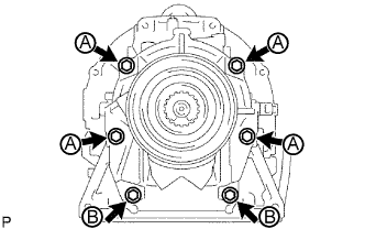
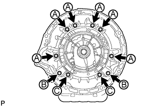
Install the valve body with the 19 bolts.
- Torque:
- 11 N*m{ 112 kgf*cm , 8 ft.*lbf }
- HINT:
- Each bolt length is indicated below.
- 36 mm (1.42 in.) for bolt A
- 25 mm (0.984 in.) for bolt B
- 45 mm (1.77 in.) for bolt C
- 50 mm (1.97 in.) for bolt D
 |
Install the detent spring and detent spring cover with the bolt.
- Torque:
- 10 N*m{ 102 kgf*cm , 7 ft.*lbf }
| 65. INSTALL TRANSMISSION WIRE |
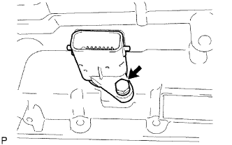 |
Coat a new O-ring with ATF, and install it to the transmission wire connector.
Install the transmission wire.
Install the bolt.
- Torque:
- 5.4 N*m{ 55 kgf*cm , 48 in.*lbf }
Connect the 9 solenoid connectors.
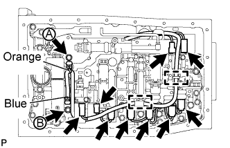 |
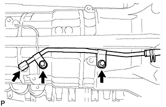
Connect the 2 ATF temperature sensors with the 2 clamps and 2 bolts.
- Torque:
- for bolt A:
- 10 N*m{ 102 kgf*cm , 7 ft.*lbf }
- for bolt B:
- 11 N*m{ 112 kgf*cm , 8 ft.*lbf }
- HINT:
- Each bolt length is indicated below.
- 12 mm (0.472 in.) for bolt A
- 36 mm (1.42 in.) for bolt B
Attach the wire harness to the 2 clamps.
| 66. INSTALL VALVE BODY OIL STRAINER ASSEMBLY |
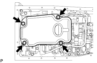 |
Coat a new O-ring with ATF, and install it to the oil strainer.
Install the oil strainer with the 4 bolts.
- Torque:
- 10 N*m{ 102 kgf*cm , 7 ft.*lbf }
| 67. INSTALL TRANSMISSION OIL CLEANER MAGNET |
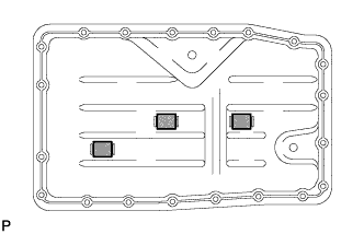 |
Install the 4 magnets.
| 68. INSTALL AUTOMATIC TRANSMISSION OIL PAN SUB-ASSEMBLY |
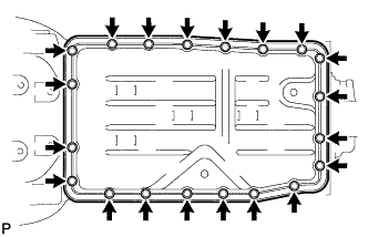 |
Install a new gasket to the oil pan.
Install the oil pan with the 20 bolts.
- Torque:
- 7.0 N*m{ 71 kgf*cm , 62 in.*lbf }
Install a new gasket and the drain plug.
- Torque:
- 20 N*m{ 204 kgf*cm , 15 ft.*lbf }
Install a new gasket and the overflow plug.
- Torque:
- 20 N*m{ 204 kgf*cm , 15 ft.*lbf }
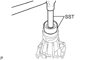
| 69. INSTALL EXTENSION HOUSING REAR OIL SEAL |
Coat the lip of a new oil seal with MP grease.
Using SST and a hammer, tap in the oil seal.
- SST
- 09316-60011
(09316-00011, 09316-00051)
- Standard depth:
- 5.4 to 5.8 mm (0.213 to 0.228 in.)
 |
| 70. INSTALL EXTENSION HOUSING DUST DEFLECTOR |
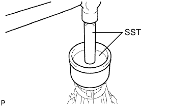 |
Using SST and a hammer, tap on a new dust deflector.
- SST
- 09223-15020
09950-70010 (09951-07100)
| 71. INSTALL EXTENSION HOUSING SUB-ASSEMBLY |
Clean the threads of the bolts and case.
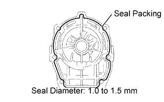
Apply seal packing to the extension housing.
- Seal packing:
- Toyota Genuine Seal Packing 1281,
Three Bond 1281 or equivalent
- Seal diameter:
- 1.0 to 1.5 mm (0.0394 to 0.0591 in.)
 |
Apply adhesive to the threads of the 6 bolts.
- Adhesive:
- Toyota Genuine Adhesive 1324,
Three Bond 1324 or equivalent
Install the extension housing with the 6 bolts.
- Torque:
- 34 N*m{ 345 kgf*cm , 25 ft.*lbf }
- HINT:
- Each bolt length is indicated below.
- 45 mm (1.77 in.) for bolt A
- 35 mm (1.38 in.) for bolt B
 |
| 72. INSTALL AUTOMATIC TRANSMISSION HOUSING |
 |
Clean the threads of the bolts and case with non-residue solvent.
Apply adhesive to the threads of the 4 bolts labeled B and C.
- Adhesive:
- Toyota Genuine Adhesive 1324,
Three Bond 1324 or equivalent
Install the transmission housing with the 10 bolts.
- Torque:
- for 14 mm head bolt A:
- 34 N*m{ 345 kgf*cm , 25 ft.*lbf }
- for 17 mm head bolt B:
- 57 N*m{ 579 kgf*cm , 42 ft.*lbf }
- for 14 mm head bolt C:
- 34 N*m{ 345 kgf*cm , 25 ft.*lbf }
| 73. INSTALL AUTOMATIC TRANSMISSION BREATHER TUBE |
 |
Coat a new O-ring with ATF and install it to the breather tube.
Install the breather tube with the 2 bolts.
- Torque:
- 5.4 N*m{ 55 kgf*cm , 48 in.*lbf }
| 74. INSTALL SPEED SENSOR |
Coat 2 new O-rings with ATF, and install one to each speed sensor.
 |
Install the 2 speed sensors.
Install the 2 bolts.
- Torque:
- 5.4 N*m{ 55 kgf*cm , 48 in.*lbf }
| 75. INSTALL OIL COOLER TUBE UNION |
 |
Coat 2 new O-rings with ATF, and install them to the 2 oil cooler tube unions.
Install the 2 oil cooler tube unions.
- Torque:
- 29 N*m{ 300 kgf*cm , 22 ft.*lbf }
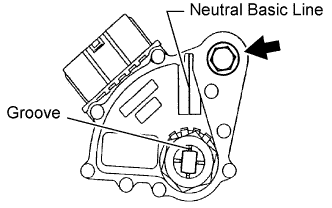
| 76. INSTALL PARK/NEUTRAL POSITION SWITCH ASSEMBLY |
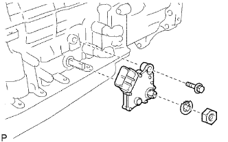 |
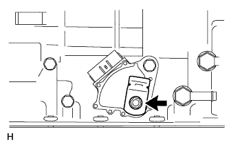
Install the park/neutral position switch to the manual valve lever shaft, and temporarily install the adjusting bolt.
Install a new lock washer and the nut.
- Torque:
- 6.9 N*m{ 70 kgf*cm , 61 in.*lbf }
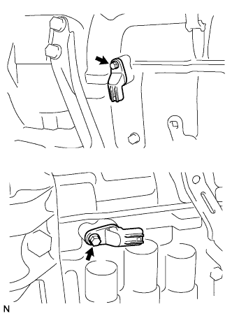
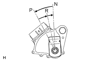
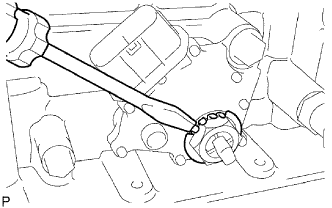
Turn the control shaft lever counterclockwise until it stops, and then turn it clockwise 2 notches to set it to the N position.
 |
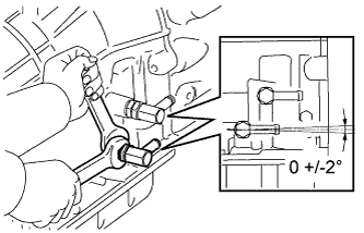
Align the neutral basic line with the switch groove as shown in the illustration, and tighten the adjusting bolt.
- Torque:
- 13 N*m{ 130 kgf*cm , 9 ft.*lbf }
 |
Using a screwdriver, bend the tabs of the lock washer.
- HINT:
- Bend at least 2 of the lock washer tabs.
 |
| 77. INSTALL TRANSMISSION CONTROL SHAFT LEVER RH |
 |
Install the control shaft lever RH with the washer and nut.
- Torque:
- 16 N*m{ 163 kgf*cm , 12 ft.*lbf }