DTC P2759 Torque Converter Clutch Pressure Control Solenoid Control Circuit Electrical (Shift Solenoid Valve SLU) |

for Preparation Click here
DESCRIPTION
The amount of current flow to the solenoid is controlled by the ECM. During the lock-up operation, if the current increases, the lock-up hydraulic pressure increases.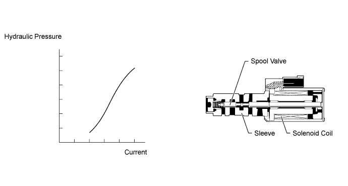
| DTC Code | DTC Detection Condition | Trouble Area |
| P2759 | Open or short is detected in the shift solenoid valve SLU circuit for 1 second or more while driving (1-trip detection logic). |
|
MONITOR DESCRIPTION
When an open or short in the shift solenoid valve SLU circuit is detected, the ECM determines that there is a malfunction. The ECM will illuminate the MIL and store the DTC.MONITOR STRATEGY
| Related DTCs | P2759: Shift solenoid valve SLU/Range check |
| Required sensors/Components | Shift solenoid valve SLU |
| Frequency of operation | Continuous |
| Duration | 1 second |
| MIL operation | Immediately |
| Sequence of operation | None |
TYPICAL ENABLING CONDITIONS
| The monitor will run whenever the following DTCs are not present | None |
| Solenoid current cut status | Not cut |
| Battery voltage | 11 V or more |
| Ignition switch | ON |
| Starter | OFF |
TYPICAL MALFUNCTION THRESHOLDS
| Solenoid status from MIC | Failure |
COMPONENT OPERATING RANGE
| Output signal duty | Less than 100% |
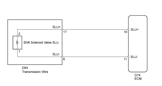
WIRING DIAGRAM
INSPECTION PROCEDURE
- NOTICE:
- Perform the universal trip to clear permanent DTCs (Click here).
| 1.INSPECT TRANSMISSION WIRE (SHIFT SOLENOID VALVE SLU) |
Disconnect the D83 transmission wire connector.
 |
Measure the resistance according to the value(s) in the table below.
- Standard Resistance:
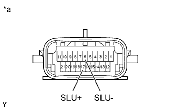
Tester Connection Condition Specified Condition 17 (SLU+) - 6 (SLU-) 20°C (68°F) 5.0 to 5.6 Ω 17 (SLU+) - Body ground Always 10 kΩ or higher 6 (SLU-) - Body ground Always 10 kΩ or higher
Text in Illustration *a Component without harness connected
(Transmission Wire)
|
| ||||
| OK | |
| 2.CHECK HARNESS AND CONNECTOR (TRANSMISSION WIRE - ECM) |
Disconnect the D74 ECM connector.
 |
Measure the resistance according to the value(s) in the table below.
- Standard Resistance:
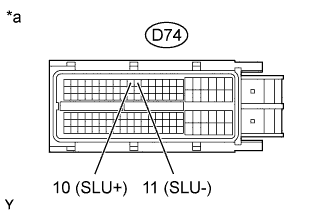
Tester Connection Condition Specified Condition D74-10 (SLU+) - D74-11 (SLU-) 20°C (68°F) 5.0 to 5.6 Ω D74-10 (SLU+) - Body ground Always 10 kΩ or higher D74-11 (SLU-) - Body ground Always 10 kΩ or higher
Text in Illustration *a Front view of wire harness connector
(to ECM)
|
| ||||
| OK | ||
| ||
| 3.INSPECT SHIFT SOLENOID VALVE SLU |
Remove shift solenoid valve SLU.
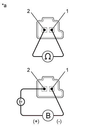 |
Measure the resistance according to the value(s) in the table below.
- Standard Resistance:
Tester Connection Condition Specified Condition 1 - 2 20°C (68°F) 5.0 to 5.6 Ω
Apply 12 V battery voltage to the shift solenoid valve and check that the valve moves and makes an operating noise.
- OK:
Measurement Condition Specified Condition - Battery positive (+) with a 21 W bulb → Terminal 2
- Battery negative (-) → Terminal 1
Valve moves and makes an operating noise - Battery positive (+) with a 21 W bulb → Terminal 2
| *a | Component without harness connected (Shift Solenoid Valve SLU) |
|
| ||||
| OK | ||
| ||