COMBUSTION TYPE POWER HEATER SYSTEM > Power Heater Switch Circuit |

for Preparation Click here
DESCRIPTION
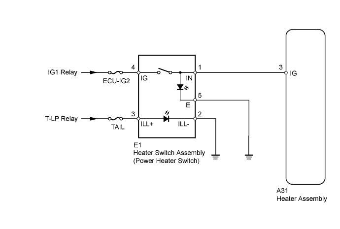
When the power heater switch is turned on, the heater assembly (ECU) sends a drive signal to the heater pump assembly. The heater assembly then receives the fuel necessary for combustion and starts operating.WIRING DIAGRAM
INSPECTION PROCEDURE
- NOTICE:
- Inspect the fuses for circuits related to this system before performing the following inspection procedure.
- HINT:
- Before performing the following procedures, check the battery and generator assembly and confirm that they are operating normally.
| 1.INSPECT HEATER SWITCH ASSEMBLY (POWER HEATER SWITCH) |
Remove the heater switch assembly (Click here).
 |
Measure the resistance according to the value(s) in the table below.
- Standard Resistance:
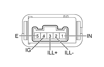
Tester Connection Switch Condition Specified Condition 4 (IG) - 1 (IN) Heater switch on Below 1 Ω 4 (IG) - 1 (IN) Heater switch off 10 kΩ or higher
Apply battery voltage to the power heater switch and check that the operation indicator comes on.
- OK:
Measurement Condition Specified Condition Battery positive (+) → Terminal 1 (IN)
Battery negative (-) → Terminal 5 (E)Indicator comes on
Apply battery voltage to the power heater switch and check that the illumination comes on.
- OK:
Measurement Condition Specified Condition Battery positive (+) → Terminal 3 (ILL+)
Battery negative (-) → Terminal 2 (ILL-)Illumination comes on
|
| ||||
| OK | |
| 2.CHECK HARNESS AND CONNECTOR (HEATER SWITCH ASSEMBLY - BODY GROUND) |
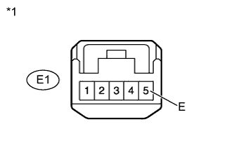
Disconnect the E1 switch connector.
 |
Measure the resistance according to the value(s) in the table below.
- Standard Resistance:
Tester Connection Condition Specified Condition E1-5 (E) - Body ground Always Below 1 Ω
Text in Illustration *1 Front view of wire harness connector
(Heater Switch Assembly [Power Heater Switch])
|
| ||||
| OK | |
| 3.CHECK HARNESS AND CONNECTOR (HEATER ASSEMBLY - BATTERY) |
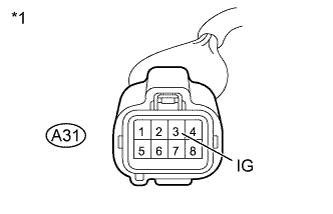
Disconnect the A31 heater connector.
 |
Measure the voltage according to the value(s) in the table below.
- Standard Voltage:
Tester Connection Switch Condition Specified Condition A31-3 (IG) - Body ground Ignition switch ON
Heater switch on11 to 14 V A31-3 (IG) - Body ground Ignition switch ON
Heater switch offBelow 1 V
Text in Illustration *1 Front view of wire harness connector
(to Heater Assembly)
|
| ||||
| OK | ||
| ||