DTC B1242 Wireless Door Lock Tuner Circuit Malfunction |

for Preparation Click here
DESCRIPTION
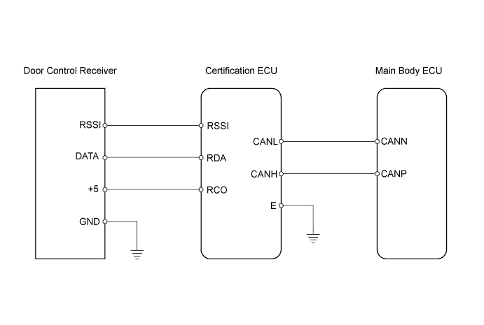
The door control receiver receives lock / unlock signals from the transmitter and sends these signals to the main body ECU via the certification ECU using the serial line.The main body ECU then activates the door lock motor on each door in accordance with these signals.
| DTC No. | DTC Detection Condition | Trouble Area |
| B1242 | One of following conditions is met:
|
|
WIRING DIAGRAM
INSPECTION PROCEDURE
| 1.CHECK WIRE HARNESS (CERTIFICATION ECU - DOOR CONTROL RECEIVER) |
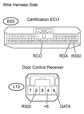 |
Disconnect the E63 ECU connector.
Disconnect the L13 receiver connector.
Measure the resistance of the wire harness side connectors.
- Standard resistance:
Tester Connection Specified Condition E63-38 (RDA) - L13-5 (DATA) Below 1 Ω E63-39 (RSSI) - L13 (RSSI) E63-29 (RCO) - L13-4 (+5) E63-38 (RDA) or L13-5 (DATA) - Body ground 10 kΩ or higher E63-39 (RSSI) or L13 (RSSI) - Body ground E63-29 (RCO) or L13-4 (+5) - Body ground
|
| ||||
| OK | |
| 2.CHECK WIRE HARNESS (MAIN BODY ECU - CERTIFICATION ECU) |
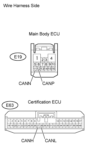 |
Disconnect the E19 and E63 ECU connectors.
Measure the resistance of the wire harness side connectors.
- Standard resistance:
Tester Connection Specified Condition E19-11 (CANP) - E63-27 (CANH) Below 1 Ω E19-12 (CANN) - E63-28 (CANL) E19-11 (CANP) or E63-27 (CANH) - Body ground 10 kΩ or higher E19-12 (CANN) or E63-28 (CANL) - Body ground
|
| ||||
| OK | |
| 3.CHECK DOOR CONTROL RECEIVER (+B TERMINAL) |
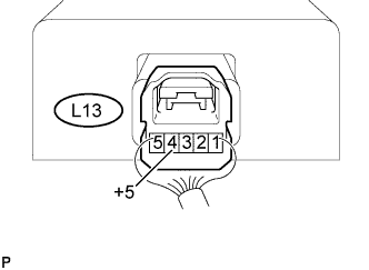 |
Measure the voltage of the connector.
- Standard voltage:
Tester Connection Condition Specified Condition L13-4 (+5) - Body ground Ignition switch off, all doors closed and transmitter switch not pressed → pressed 5 to below 1 V → 5 V
|
| ||||
| OK | |
| 4.CHECK WIRE HARNESS (DOOR CONTROL RECEIVER - BODY GROUND) |
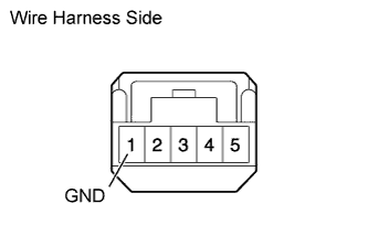 |
Disconnect the L13 receiver connector.
Measure the resistance of the wire harness side connector.
- Standard resistance:
Tester Connection Specified Condition L13-1 (GND) - Body ground Below 1 Ω
|
| ||||
| OK | |
| 5.REPLACE DOOR CONTROL RECEIVER |
Temporarily replace the door control receiver with a new or normally functioning one (Click here, Click here).
Perform the REGISTRATION procedures.
| NEXT | |
| 6.CHECK FOR DTC |
Clear the DTC (Click here).
Check if the same DTC is detected.
- OK:
- DTC B1242 is not output.
|
| ||||
| NG | |
| 7.CHECK ECU AGGREGATION BOX (OPERATION) |
Temporarily replace the ECU aggregation box with a new or normally functioning one.
Check if the same DTC is detected.
- OK:
- DTC B1242 is not output.
|
| ||||
| NG | ||
| ||