WIPER AND WASHER SYSTEM (w/ Rain Sensor) > Wiper Motor Power Source Circuit |

for Preparation Click here
DESCRIPTION
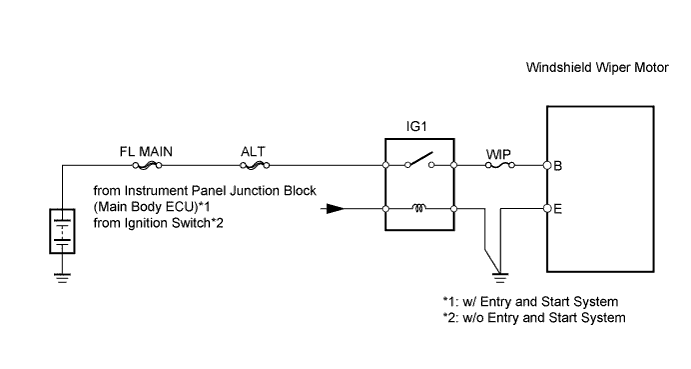
This circuit provides power to the windshield wiper motor.WIRING DIAGRAM
INSPECTION PROCEDURE
| 1.INSPECT FUSE (WIP) |
Remove the WIP fuse from the instrument panel junction block.
Measure the resistance of the fuse.
- Standard resistance:
- Below 1 Ω
|
| ||||
| OK | |
| 2.INSPECT IG1 RELAY |
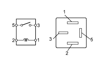 |
Remove the IG1 relay from the instrument panel junction block.
Measure the resistance of the relay.
- Standard resistance:
Tester Connection Specified Condition 3 - 5 10 kΩ or higher Below 1 Ω
(when battery voltage is applied to terminals 1 and 2)
|
| ||||
| OK | |
| 3.CHECK WIRE HARNESS (MOTOR - BATTERY AND BODY GROUND) |
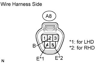 |
Disconnect the A8 motor connector.
Measure the voltage of the wire harness side connector.
- Standard voltage:
Tester Connection Switch Condition Specified Condition A8-2 (B) - Body ground Ignition switch on (IG) 10 to 14 V
Measure the resistance of the wire harness side connector.
- Standard resistance:
for LHD Tester Connection Specified Condition A6-4 (E) - Body ground Below 1 Ω
- for RHD:
Tester Connection Specified Condition A6-5 (E) - Body ground Below 1 Ω
|
| ||||
| OK | ||
| ||