CAN COMMUNICATION SYSTEM > Air Conditioning Amplifier Communication Stop Mode |

for Preparation Click here
DESCRIPTION
| Detection Item | Symptom | Trouble Area |
| Air Conditioning Amplifier Communication Stop Mode | Either condition is met:
|
|
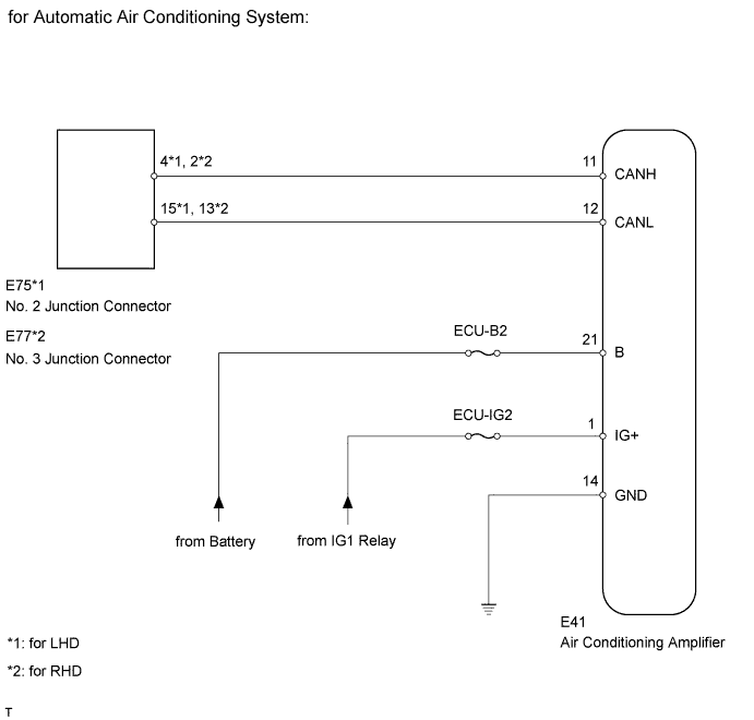
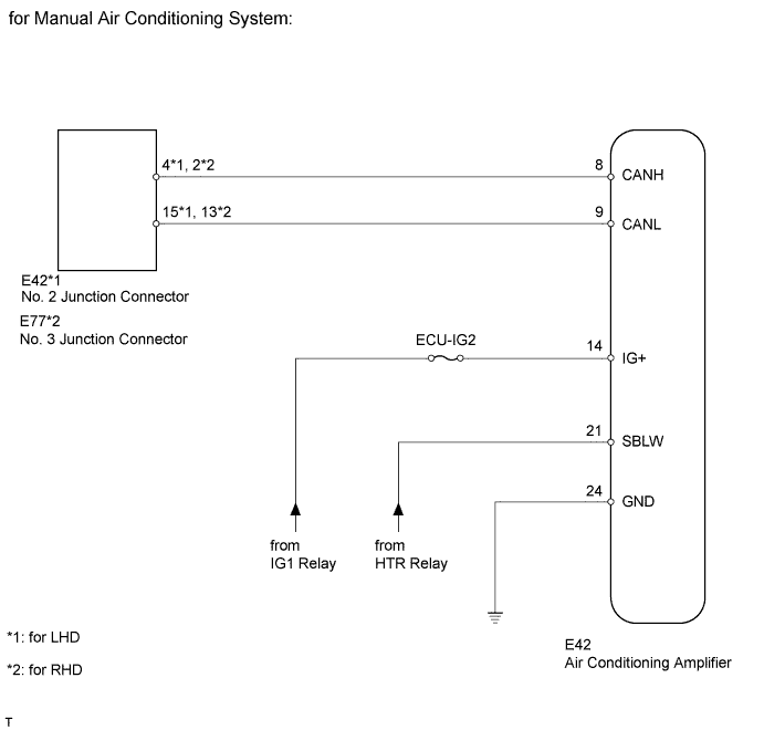
WIRING DIAGRAM
INSPECTION PROCEDURE
- NOTICE:
- Turn the ignition switch off before measuring the resistance of the main wire and the branch wire.
- After the ignition switch is turned off, check that the key reminder warning system and light reminder buzzer are not in operation.
- Before measuring the resistance, leave the vehicle for at least 1 minute and do not operate the ignition switch, any switches or doors. If doors need to be opened in order to check connectors, open the doors and leave them open.
- HINT:
- Operating the ignition switch, any switches or any doors triggers related ECU and sensor communication with the CAN, which causes resistance variation.
| 1.DISCONNECT CABLE FROM NEGATIVE BATTERY TERMINAL |
Disconnect the cable from the negative (-) battery terminal before measuring the resistance of the main wire and the branch wire.
- CAUTION:
- Wait at least 90 seconds after disconnecting the cable from the negative (-) battery terminal to disable the SRS system.
- NOTICE:
- w/ Navigation System (for HDD):
After the ignition switch is turned off, the HDD navigation system requires approximately a minute to record various types of memory and settings. As a result, after turning the ignition switch off, wait a minute or more before disconnecting the cable from the negative (-) battery terminal. - When disconnecting the cable, some systems need to be initialized after the cable is reconnected.
| NEXT | |
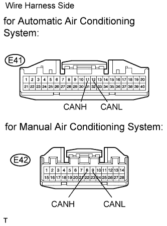
| 2.CHECK CAN BUS LINE FOR DISCONNECTION (AIR CONDITIONING AMPLIFIER BRANCH WIRE) |
Disconnect the E41*1 or E42*2 air conditioning amplifier connector.
- *1: for Automatic Air Conditioning System
- *2: for Manual Air Conditioning System
- *1: for Automatic Air Conditioning System
 |
Measure the resistance according to the value(s) in the table below.
- Standard Resistance:
- for Automatic Air Conditioning System:
Tester Connection Switch Condition Specified Condition E41-11 (CANH) - E41-12 (CANL) Ignition switch off 54 to 69 Ω - for Manual Air Conditioning System:
Tester Connection Switch Condition Specified Condition E42-8 (CANH) - E42-9 (CANL) Ignition switch off 54 to 69 Ω
|
| ||||
| OK | |
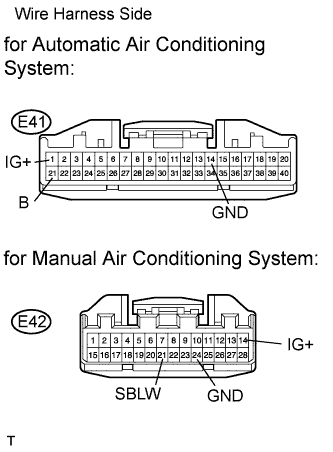
| 3.CHECK HARNESS AND CONNECTOR (AIR CONDITIONING AMPLIFIER - BATTERY AND BODY GROUND) |
Connect the cable to the negative (-) battery terminal.
- NOTICE:
- When disconnecting the cable, some systems need to be initialized after the cable is reconnected.
Disconnect the E41*1 or E42*2 air conditioning amplifier connectors.
- *1: for Automatic Air Conditioning System
- *2: for Manual Air Conditioning System
- *1: for Automatic Air Conditioning System
 |
Measure the resistance according to the value(s) in the table below.
- Standard Resistance:
- for Automatic Air Conditioning System:
Tester Connection Condition Specified Condition E41-14 (GND) - Body ground Always Below 1 Ω - for Manual Air Conditioning System:
Tester Connection Condition Specified Condition E42-24 (GND) - Body ground Always Below 1 Ω
Measure the voltage according to the value(s) in the table below.
- Standard Voltage:
- for Automatic Air Conditioning System:
Tester Connection Switch Condition Specified Condition E41-21 (B) - Body ground Always 11to 14 V E41-1 (IG+) - Body ground Ignition switch on (IG) 11to 14 V - for Manual Air Conditioning System:
Tester Connection Switch Condition Specified Condition E42-14 (IG+) - Body ground Ignition switch on (IG) 11 to 14 V
|
| ||||
| OK | ||
| ||