INTERCOOLER > INSTALLATION |

for Preparation Click here
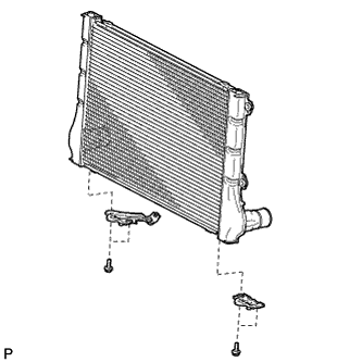
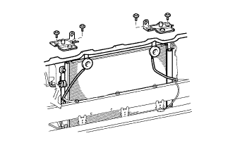
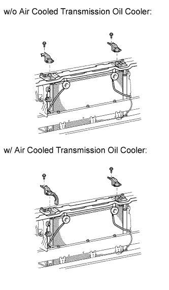
| 1. INSTALL NO. 2 RADIATOR SUPPORT |
Install the 2 radiator supports with the 4 bolts.
- Torque:
- 11 N*m{ 112 kgf*cm , 8 ft.*lbf }
 |
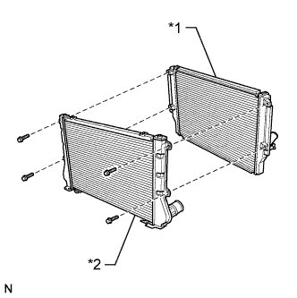
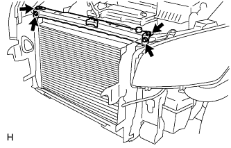
| 2. INSTALL RADIATOR AND INTERCOOLER |
- NOTICE:
- When reusing an air hose or air tube, check that there is no damage or foreign matter. If necessary, clean the part.
Align the intercooler with the radiator, and then install the intercooler to the radiator with the 4 bolts.
- Torque:
- 11 N*m{ 112 kgf*cm , 8 ft.*lbf }
Text in Illustration *1 Radiator *2 Intercooler
 |
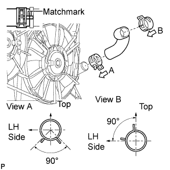
Temporarily install the No. 2 air tube to the intercooler and No. 3 air hose.
 |
Install the bolt.
- Torque:
- 31 N*m{ 316 kgf*cm , 23 ft.*lbf }
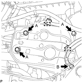
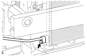
Tighten the 2 clamps as shown in the illustration.
- Torque:
- 6.5 N*m{ 66 kgf*cm , 58 in.*lbf }
- HINT:
- The direction of the hose clamp is indicated in the illustration.
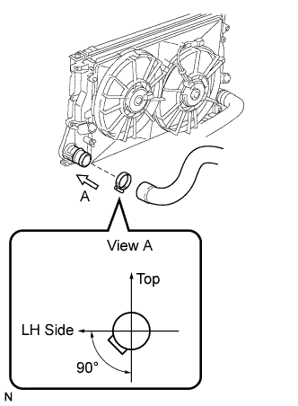
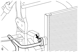
Install the No. 2 air hose to the intercooler. Tighten the clamp as shown in the illustration.
- Torque:
- 6.5 N*m{ 66 kgf*cm , 58 in.*lbf }
- HINT:
- The direction of the hose clamp is indicated in the illustration.
 |
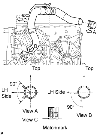
Install the radiator and intercooler assembly to the vehicle.
Connect the No. 2 and No. 3 air hoses to the engine.
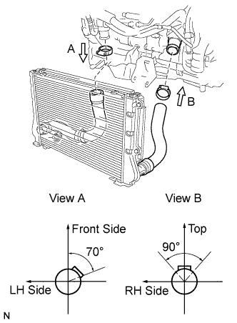 |
Tighten the 2 clamps as shown in the illustration.
- Torque:
- 6.5 N*m{ 66 kgf*cm , 58 in.*lbf }
- HINT:
- The direction of each hose clamp is indicated in the illustration.
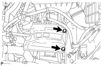
Attach the 9 wire harness clamps and connect the 3 connectors.
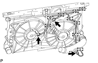 |
Connect the vacuum hose to the intake manifold.
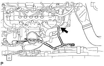 |
| 3. INSTALL OUTLET RADIATOR HOSE |
 |
Align the matchmarks and install the outlet radiator hose.
- HINT:
- The direction of each hose clamp is indicated in the illustration.
| 4. INSTALL INLET RADIATOR HOSE |
 |
Align the matchmarks, install the inlet radiator hose and connect the No. 5 water by-pass hose to the radiator.
- HINT:
- The direction of each hose clamp is indicated in the illustration.
| 5. INSTALL UPPER RADIATOR SUPPORT |
 |
Install the upper radiator support with the 4 bolts.
- Torque:
- 29 N*m{ 296 kgf*cm , 21 ft.*lbf }
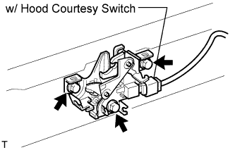
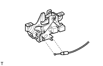
| 6. INSTALL HOOD LOCK ASSEMBLY (for LHD) |
Connect the cable to the lock.
 |
Install the lock with the 3 bolts.
- Torque:
- 8.0 N*m{ 82 kgf*cm , 71 in.*lbf }
Adjust the lock.
w/ Hood courtesy switch:
Connect the connector.
| 7. INSTALL HOOD LOCK ASSEMBLY (for RHD) |
Connect the cable to the lock.
 |
Install the lock with the 3 bolts.
- Torque:
- 8.0 N*m{ 82 kgf*cm , 71 in.*lbf }
|
Adjust the lock.
w/ Hood courtesy switch:
Connect the connector.
| 8. INSTALL WATER BY-PASS HOSE |
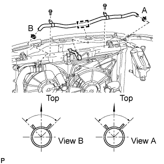 |
Connect the water by-pass hose to the radiator and radiator reservoir.
- HINT:
- The direction of each hose clamp is indicated in the illustration.
Install the water by-pass hose with the 2 bolts to the upper radiator support.
- Torque:
- 5.0 N*m{ 51 kgf*cm , 44 in.*lbf }
Attach the water by-pass hose to the hose clamp.
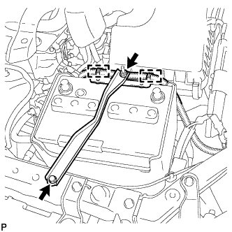
| 9. INSTALL BATTERY BRACKET REINFORCEMENT |
Install the battery bracket reinforcement with the 2 bolts.
- Torque:
- 20 N*m{ 204 kgf*cm , 15 ft.*lbf }
 |
| 10. INSTALL FRONT BATTERY BRACKET |
Install the front battery bracket with the 4 bolts.
- Torque:
- for bolt (A):
- 20 N*m{ 204 kgf*cm , 15 ft.*lbf }
- for bolt (B):
- 19 N*m{ 196 kgf*cm , 14 ft.*lbf }
 |
Attach the 2 wire harness clamps.
| 11. INSTALL BATTERY TRAY |
| 12. INSTALL BATTERY |
| 13. INSTALL BATTERY CLAMP SUB-ASSEMBLY |
Attach the hook of the battery clamp to the front battery bracket.
 |
Partially tighten the nut and temporarily install the bolt.
Adjust the battery clamp position.
Tighten the nut and bolt.
- Torque:
- for bolt:
- 17 N*m{ 168 kgf*cm , 12 ft.*lbf }
- for nut:
- 4.9 N*m{ 50 kgf*cm , 43 in.*lbf }
Attach the 2 wire harness clamps.
| 14. INSTALL COOLER CONDENSER ASSEMBLY (w/ Air Conditioning System) |
Install the cooler condenser.
 |
| 15. INSTALL NO. 1 RADIATOR SUPPORT |
 |
Install the 2 radiator supports with the 4 bolts.
- Torque:
- 5.5 N*m{ 56 kgf*cm , 49 in.*lbf }
| 16. INSTALL UPPER RADIATOR SUPPORT BRACKET |
 |
Install the 2 brackets with the 2 bolts.
- Torque:
- 19 N*m{ 194 kgf*cm , 14 ft.*lbf }
| 17. CONNECT LIQUID PIPE SUB-ASSEMBLY (w/ Air Conditioning System) |
 |
Remove the attached vinyl tape from the pipe and the connecting part of the cooler condenser.
Sufficiently apply compressor oil to a new O-ring and the fitting surface of the pipe joint.
- Compressor oil:
- ND-OIL 8 or equivalent
Install the O-ring on the cooler refrigerant liquid pipe.
Install the cooler refrigerant liquid pipe on the cooler condenser with the bolt.
- Torque:
- 5.4 N*m{ 55 kgf*cm , 48 in.*lbf }
| 18. CONNECT DISCHARGE HOSE SUB-ASSEMBLY (w/ Air Conditioning System) |
 |
Remove the attached vinyl tape from the hose and the connecting part of the cooler condenser.
Sufficiently apply compressor oil to a new O-ring and the fitting surface of the hose joint.
- Compressor oil:
- ND-OIL 8 or equivalent
Install the O-ring on the cooler refrigerant discharge hose.
Install the cooler refrigerant discharge hose on the cooler condenser with the bolt.
- Torque:
- 5.4 N*m{ 55 kgf*cm , 48 in.*lbf }
| 19. CONNECT CABLE TO POSITIVE BATTERY TERMINAL |
| 20. CONNECT CABLE TO NEGATIVE BATTERY TERMINAL |
| 21. ADD ENGINE COOLANT |
Tighten the radiator drain cock plug by hand.
Tighten the cylinder block drain cock plug.
- Torque:
- 13 N*m{ 130 kgf*cm , 9 ft.*lbf }
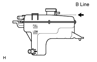
Add TOYOTA Super Long Life Coolant (SLLC) to the radiator reservoir filler opening.
Continue adding TOYOTA SLLC until it is filled to the B line.
- HINT:
- The B line is the lower edge of the inner wall of the filler neck.
- Standard Capacity:
Item Specified Condition w/o Combustion Type Power Heater 7.3 liters
(7.7 US qts, 6.4 Imp. qts)w/ Combustion Type Power Heater 7.7 liters
(8.1 US qts, 6.8 Imp. qts)
- HINT:
- TOYOTA vehicles are filled with TOYOTA SLLC at the factory. In order to avoid damage to the engine cooling system and other technical problems, only use TOYOTA SLLC or similar high quality ethylene glycol based non-silicate, non-amine, non-nitrite, non-borate coolant with long-life hybrid organic acid technology (coolant with long-life hybrid organic acid technology is a combination of low phosphates and organic acids).
- NOTICE:
- Never use water as a substitute for engine coolant.
 |
Press the inlet and outlet radiator hoses several times by hand, and then check the level of the coolant.
If the coolant level drops below the B line, add TOYOTA SLLC to the B line.
Install the radiator reservoir cap.
Start the engine, and warm it up until the cooling fan operates.
Set the air conditioning as follows while warming up the engine.
Measurement Condition Item Condition Manual Air Conditioning System Fan speed - Any setting except "OFF" Temperature - Toward WARM
Air conditioning switch "OFF"Automatic Air Conditioning System Temperature - Toward MAX
Air conditioning switch "OFF"Maintain the engine speed at 2000 to 2500 rpm and warm up the engine until the cooling fan operates.
- NOTICE:
- Make sure that the radiator reservoir still has some coolant in it.
- Pay attention to the needle of the water temperature meter. Make sure that the needle does not show an abnormally high temperature.
- If there is not enough coolant, the engine may burn out or overheat.
- Immediately after starting the engine, if the radiator reservoir does not have any coolant, perform the following: 1) stop the engine, 2) wait until the coolant has cooled down, and 3) add coolant until the coolant is filled to the B line.
- Until the coolant level has stabilized, run the engine at 2000 rpm.
Press the inlet and outlet radiator hoses several times by hand to bleed air.
- CAUTION:
- When pressing the radiator hoses:
- Wear protective gloves.
- Be careful as the radiator hoses are hot.
- Keep your hands away from the radiator fan.
Stop the engine and wait until the coolant cools down to ambient temperature.
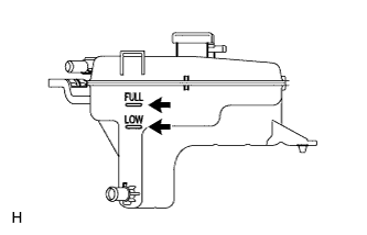
Check that the coolant level is between the FULL and LOW line.
If the coolant level is below the LOW line, repeat all of the procedures above.
If the coolant level is above the FULL line, drain coolant so that the coolant level is between the FULL and LOW line.
 |
| 22. INSPECT FOR COOLANT LEAK |
Remove the radiator reservoir cap.
- CAUTION:
- To avoid the danger of being burned, do not remove the radiator reservoir cap while the engine and radiator are still hot. Thermal expansion will cause hot engine coolant and steam to blow out from the radiator.
Fill the radiator with coolant, and then attach a radiator cap tester.
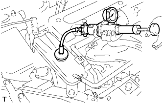 |
Warm up the engine.
Pump the radiator cap tester to 118 kPa (1.2 kgf/cm2, 17 psi), and then check that the pressure does not drop.
If the pressure drops, check the hoses, radiator and water pump for leakage.
If there are no signs of external coolant leaks, check the heater core, cylinder block and head.
Reinstall the radiator cap.
| 23. CHARGE REFRIGERANT (w/ Air Conditioning System) |
Perform vacuum purging using a vacuum pump.
Charge refrigerant HFC-134a (R134a).
- Standard:
- 430 +-30 g (15.2 +-1.1 oz.)
- SST
- 09985-20010
(09985-02130, 09985-02150, 09985-02090, 09985-02110, 09985-02010, 09985-02050, 09985-02060, 09985-02070)
- NOTICE:
- Do not operate the cooler compressor before charging refrigerant as the cooler compressor will not work properly without any refrigerant, and will overheat.
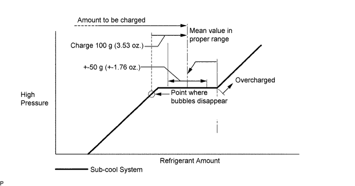
- Approximately 100 g (3.53 oz.) of refrigerant may need to be charged after bubbles disappear. The refrigerant amount should be checked by measuring its quantity, and not with the sight glass.
| 24. WARM UP ENGINE (w/ Air Conditioning System) |
Perform vacuum purging using a vacuum pump.
Charge refrigerant HFC-134a (R134a).
- Standard:
- 430 +-30 g (15.2 +-1.1 oz.)
- SST
- 09985-20010
(09985-02130, 09985-02150, 09985-02090, 09985-02110, 09985-02010, 09985-02050, 09985-02060, 09985-02070)
- NOTICE:
- Do not operate the cooler compressor before charging refrigerant as the cooler compressor will not work properly without any refrigerant, and will overheat.
- Approximately 100 g (3.53 oz.) of refrigerant may need to be charged after bubbles disappear. The refrigerant amount should be checked by measuring its quantity, and not with the sight glass.
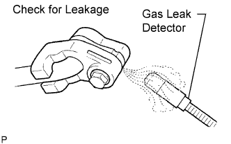
| 25. INSPECT FOR REFRIGERANT LEAK (w/ Air Conditioning System) |
After recharging the refrigerant gas, check for refrigerant gas leakage using a halogen leak detector.
Perform the operation under these conditions:
- Stop the engine.
- Secure good ventilation (the gas leak detector may react to volatile gases other than refrigerant, such as evaporated gasoline or exhaust gas).
- Repeat the test 2 or 3 times.
- Make sure that some refrigerant remains in the refrigeration system. When compressor is off: approximately 392 to 588 kPa (4 to 6 kgf/cm2, 57 to 85 psi)
- Stop the engine.
Using a gas leak detector, check the refrigerant line for leakage.
 |
If a gas leak is not detected on the drain hose, remove the blower motor control (blower resistor) from the cooling unit. Insert the gas leak detector sensor into the unit and perform the test.
Disconnect the connector and leave the pressure switch on for approximately 20 minutes. Bring the gas leak detector close to the pressure switch and perform the test.
| 26. INSTALL REAR ENGINE UNDER COVER RH |
Install the under cover with the 2 clips.
| 27. INSTALL REAR ENGINE UNDER COVER LH |
Install the under cover with the 2 clips.
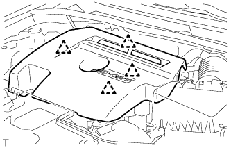
| 28. INSTALL NO. 1 ENGINE UNDER COVER |
Install the engine under cover with the 6 bolts and 10 clips.
| 29. INSTALL NO. 1 ENGINE COVER |
Attach the 4 clips to install the engine cover.
 |
| 30. INSTALL FRONT BUMPER REINFORCEMENT |
w/ Under Guard:
Install the front bumper reinforcement (Click here).
w/o Under Guard:
Install the front bumper reinforcement (Click here).