MANUAL TRANSAXLE UNIT > REASSEMBLY |

for Preparation Click here
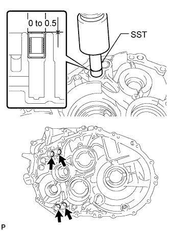
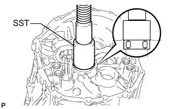
| 1. INSTALL SHIFT FORK SHAFT BEARING |
Using SST and a press, press in the 4 bearings.
- SST
- 09820-00031
- Standard clearance:
- 0 to 0.5 mm (0.000 to 0.020 in.)
 |
| 2. INSTALL OUTPUT SHAFT COVER |
Install the output shaft cover, as shown in the illustration.
 |
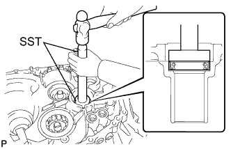
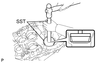
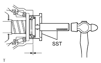
| 3. INSTALL NO. 2 OUTPUT SHAFT FRONT BEARING |
Using SST and hammer, tap in the bearing.
- SST
- 09950-70010
(09951-07100, 09951-00710)
 |
| 4. INSTALL OUTPUT SHAFT COVER |
Install the output shaft cover, as shown in the illustration.
 |
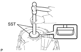
| 5. INSTALL OUTPUT SHAFT FRONT BEARING |
Coat a new bearing with gear oil.
 |
Using SST and a press, press in the bearing.
- SST
- 09223-15020
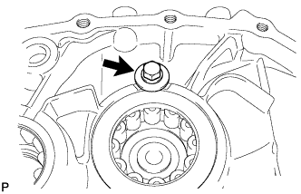
| 6. INSTALL BEARING LOCK PLATE BOLT |
Install the bearing lock plate bolt.
- Torque:
- 11 N*m{ 115 kgf*cm , 8 ft.*lbf }
 |
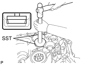
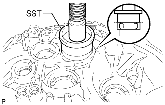
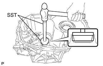
| 7. INSTALL TRANSAXLE CASE OIL SEAL |
Using SST and a hammer, tap in a new oil seal to the front transaxle case.
- SST
- 09950-60010
(09951-00580)
- Standard depth:
- 4.4 to 5.0 mm (0.173 to 0.197 in.)
 |
Coat the lip of the oil seal with MP grease.
| 8. INSTALL INPUT SHAFT FRONT BEARING |
Coat a new bearing with gear oil.
 |
Using SST and a press, press in the bearing.
- SST
- 09223-00010
| 9. INSTALL BEARING LOCK PLATE BOLT |
Install the lock plate bolt.
- Torque:
- 11 N*m{ 115 kgf*cm , 8 ft.*lbf }
 |
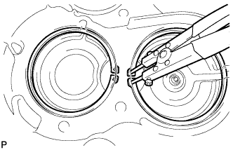
| 10. INSTALL INPUT SHAFT REAR BEARING SHAFT SNAP RING |
Using snap ring pliers, install the 2 snap rings.
 |
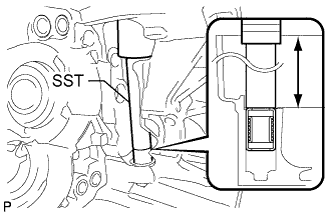
| 11. INSTALL SHIFT AND SELECT LEVER SHAFT NEEDLE ROLLER BEARING |
Using SST and a press, press in a new needle roller bearing.
- SST
- 09285-76010
- Standard clearance:
- 177.8 to 178.7 mm (7.000 to 7.035 in.)
 |
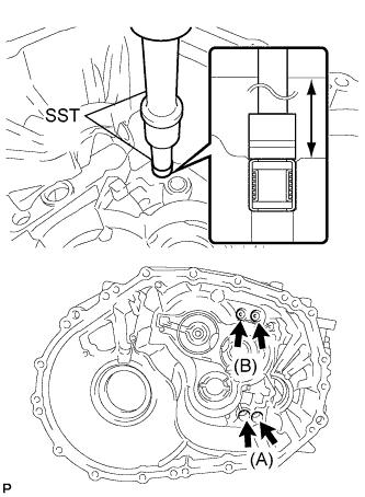
| 12. INSTALL SHIFT FORK SHAFT BEARING |
Using SST and a press, press in 4 new bearings.
- SST
- 09307-12010
09820-00031
- Standard clearance:
- A:
- 168.2 to 169.3 mm (6.622 to 6.665 in.)
- B:
- 162.2 to 163.3 mm (6.386 to 6.429 in.)
 |
| 13. INSTALL FRONT DIFFERENTIAL CASE FRONT TAPERED ROLLER BEARING |
Using SST and a hammer, tap in the tapered roller bearing.
- SST
- 09950-70010
(09951-00910, 09951-07150)
 |
| 14. INSTALL FRONT DIFFERENTIAL CASE REAR SHIM |
Install the shim into the transmission case.
 |
| 15. INSTALL FRONT DIFFERENTIAL CASE REAR TAPERED ROLLER BEARING |
Using SST and a hammer, install the tapered roller bearing.
- SST
- 09950-60010
(09951-00910)
09950-70010 (09951-07100)
 |
| 16. ADJUST DIFFERENTIAL SIDE BEARING PRELOAD |
Install the differential case to the front transaxle case.
 |
Install the transmission case to the transaxle case with the 12 bolts.
- Torque:
- 29 N*m{ 299 kgf*cm , 22 ft.*lbf }
 |
Install the 6 bolts of the transaxle case side.
- Torque:
- 29 N*m{ 299 kgf*cm , 22 ft.*lbf }
 |
Turn the differential case in both directions to smooth its movement.
Using SST and a torque wrench, measure the starting preload.
- SST
- 09564-32011
- Standard new bearing preload:
- 0.96 to 2.38 N*m (9.8 to 24.3 kgf*cm, 8.5 to 21.07 in.*lbf)
 |
Select a new shim.
- Standard shim thickness:
Mark Thickness Mark Thickness Mark Thickness 0 1.99 to 2.01 mm (0.0783 to 0.0791 in.) 6 2.29 to 2.31 mm (0.0902 to 0.0909 in.) C 2.59 to 2.61 mm (0.1020 to 0.1028 in.) 1 2.04 to 2.06 mm (0.0803 to 0.0811 in.) 7 2.34 to 2.36 mm (0.0921 to 0.0929 in.) D 2.64 to 2.66 mm (0.1039 to 0.1047 in.) 2 2.09 to 2.11 mm (0.0823 to 0.0831 in.) 8 2.39 to 2.41 mm (0.0941 to 0.0949 in.) E 2.69 to 2.71 mm (0.1059 to 0.1067 in.) 3 2.14 to 2.16 mm (0.0843 to 0.0850 in.) 9 2.44 to 2.46 mm (0.0961 to 0.0969 in.) F 2.74 to 2.76 mm (0.1079 to 0.1087 in.) 4 2.19 to 2.21 mm (0.0862 to 0.0870 in.) A 2.49 to 2.51 mm (0.0981 to 0.0988 in.) G 2.79 to 2.81 mm (0.1098 to 0.1106 in.) 5 2.24 to 2.26 mm (0.0882 to 0.0890 in.) B 2.54 to 2.56 mm (0.1000 to 0.1008 in.) H 2.84 to 2.86 mm (0.1118 to 0.1126 in.)
Remove the transmission case from the front transaxle case.
Remove the 18 bolts and transmission case.
| 17. INSTALL OUTPUT SHAFT NO. 2 REAR BEARING OUTER RACE |
Install the shim onto the transmission case.
- HINT:
- When reusing the output shaft rear tapered roller bearing, first install a shim of the same thickness as the original. When installing a new output shaft front bearing, first select and install a shim which is thinner than the original.
 |
Using SST and a press, press in the bearing outer race.
- SST
- 09950-60010
(09951-00650)
09950-70010 (09951-07200)
 |
| 18. ADJUST NO. 2 OUTPUT SHAFT REAR BEARING PRELOAD |
Install the No. 2 output shaft and differential case onto the front transaxle case.
 |
Install the transmission case to the front transaxle case with the 12 bolts.
- Torque:
- 29 N*m{ 299 kgf*cm , 22 ft.*lbf }
|
Install the 6 bolts of the transaxle case side.
- Torque:
- 29 N*m{ 299 kgf*cm , 22 ft.*lbf }
|
Measure the No. 2 output shaft rear bearing preload. Subtract the value of the differential side bearing preload from the measured No. 2 output shaft rear bearing preload. Select a shim that will set the preload within the specified range below and install the shim.
- Standard new bearing preload:
- 4.4 to 6.2 N*m (45 to 63 kgf*cm, 39 to 55 in.*lbf)
- Standard shim thickness:
Mark Thickness Mark Thickness Mark Thickness A 1.79 to 1.81 mm (0.0705 to 0.0713 in.) G 2.09 to 2.11 mm (0.0823 to 0.0831 in.) N 2.39 to 2.41 mm (0.0941 to 0.0949 in.) B 1.84 to 1.86 mm (0.0724 to 0.0732 in.) H 2.14 to 2.16 mm (0.0843 to 0.0850 in.) P 2.44 to 2.46 mm (0.0961 to 0.0969 in.) C 1.89 to 1.91 mm (0.0744 to 0.0752 in.) J 2.19 to 2.21 mm (0.0862 to 0.0870 in.) Q 2.49 to 2.51 mm (0.0980 to 0.0988 in.) D 1.94 to 1.96 mm (0.0764 to 0.0772 in.) K 2.24 to 2.26 mm (0.0882 to 0.0890 in.) R 2.54 to 2.56 mm (0.1000 to 0.1008 in.) E 1.99 to 2.01 mm (0.0783 to 0.0791 in.) L 2.29 to 2.31 mm (0.0902 to 0.0909 in.) S 2.59 to 2.61 mm (0.1020 to 0.1028 in.) F 2.04 to 2.06 mm (0.0803 to 0.0811 in.) M 2.34 to 2.36 mm (0.0921 to 0.0929 in.) T 2.64 to 2.66 mm (0.1039 to 0.1047 in.)
 |
Remove the transmission case.
Remove the 18 bolts and transmission case.
Remove the output shaft assembly from the front transaxle case.
Remove the differential case from the front transaxle case.
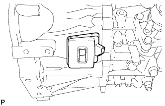
| 19. INSTALL TRANSMISSION MAGNET |
Clean and install the transmission magnet onto the front transaxle case.
 |
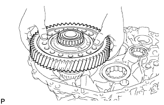
| 20. INSTALL FRONT DIFFERENTIAL CASE ASSEMBLY |
Coat the differential case tapered roller bearing with gear oil, and install it onto the front transaxle case.
|
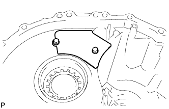
| 21. INSTALL TRANSMISSION OIL SEPARATOR |
Install the oil separator onto the front transaxle case with the 2 bolts.
- Torque:
- 8.5 N*m{ 87 kgf*cm , 75 in.*lbf }
 |
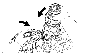
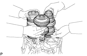
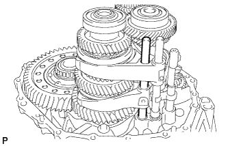
| 22. INSTALL INPUT SHAFT, NO. 1 OUTPUT SHAFT AND NO. 2 OUTPUT SHAFT |
Install the 3 shafts at the same time.
 |
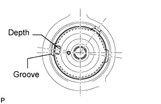
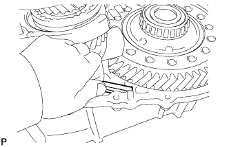
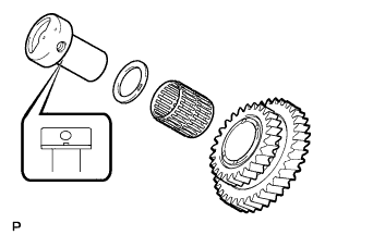
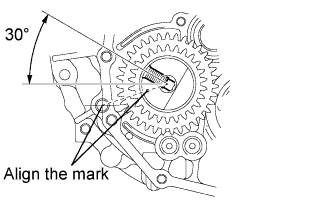
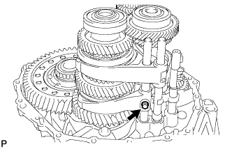
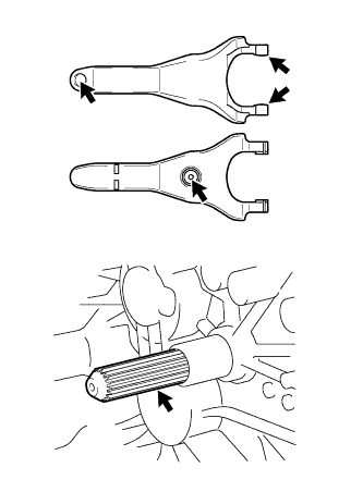
| 23. INSTALL REVERSE IDLER GEAR |
Coat the reverse idler gear, needle roller bearing and reverse idler thrust washer with MP grease, and install them to the reverse idler gear shaft.
- HINT:
- Make sure that the protruding part on the reverse idler thrust washer is fitted into the groove of the reverse idler shaft.
 |
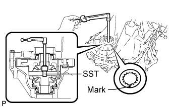
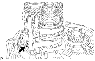
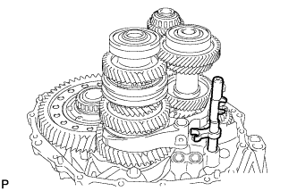
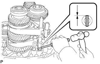
Install the reverse idler gear shaft by sliding and lifting it.
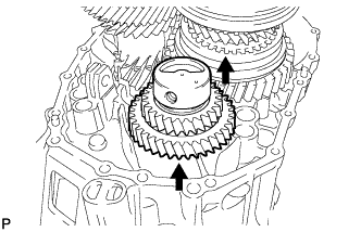 |
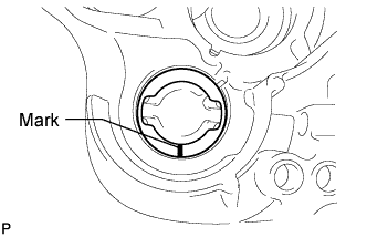
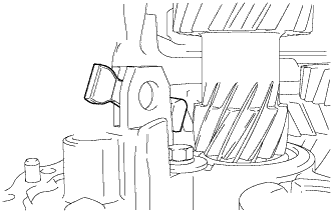
Align the mark of the reverse idler gear shaft with the hole of the bolt.
 |
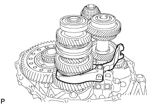
| 24. INSTALL REVERSE SHIFT FORK |
Install the reverse shift fork onto the No. 4 hub sleeve.
 |
| 25. INSTALL NO. 3 GEAR SHIFT FORK |
Install the No. 3 gear shift fork onto the No. 3 hub sleeve.
 |
| 26. INSTALL 5TH AND 6TH SHIFT FORK SHAFT |
Install the 5th and 6th shift fork shaft onto the front transaxle case.
 |
Install the bolt into the No. 3 gear shift fork.
- Torque:
- 20 N*m{ 204 kgf*cm , 14 ft.*lbf }
 |
| 27. INSTALL REVERSE SHIFT FORK SHAFT |
Install the reverse shift fork shaft into the front transaxle case.
 |
Install the bolt into the No. 4 gear shift fork.
- Torque:
- 20 N*m{ 204 kgf*cm , 14 ft.*lbf }
 |
| 28. INSTALL SHIFT ARM |
Install the shaft arm into the front transaxle case.
 |
| 29. INSTALL NO.1 GEAR SHIFT FORK |
Install the No. 1 gear shift fork onto the No. 1 hub sleeve.
 |
| 30. INSTALL NO. 5 GEAR SHIFT FORK SHAFT |
Install the No. 3 gear shift head to the No. 5 gear shift fork shaft.
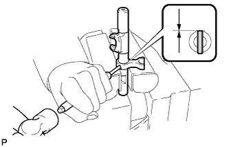 |
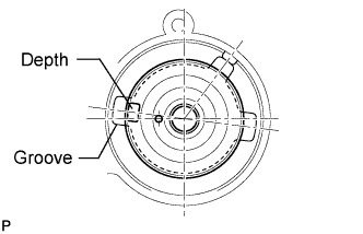
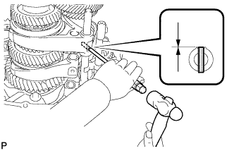
Using a pin punch and hammer, tap the slotted pin into the No. 3 gear shift head.
- Standard depth:
- -0.5 to 0.5 mm (-0.0197 to 0.0197 in.)
Install the No. 5 gear shift fork shaft into the front transaxle case.
 |
Assemble the shift arm and No. 5 gear shift fork shaft.
 |
Install the shift arm pin into the shift arm.
 |
Using a brass bar and hammer, tap a new E-ring onto the shift arm pin.
 |
| 31. INSTALL NO. 2 GEAR SHIFT FORK |
Install the No. 2 gear shift fork onto the No. 2 hub sleeve.
 |
| 32. INSTALL 3RD AND 4TH SHIFT FORK SHAFT |
Install the No. 3 gear shift head to the 3rd and 4th shift fork shaft.
 |
Install the 3rd and 4th shift fork shaft to the transmission case.
Using a pin punch and hammer, tap a new slotted spring pin into the No. 2 gear shift fork.
- Standard depth:
- -0.5 to 0.5 mm (-0.0197 to 0.0197 in.)
 |
Using a pin punch and hammer, tap the slotted spring pin into the No. 3 gear shift head.
- Standard depth:
- -0.5 to 0.5 mm (-0.0197 to 0.0197 in.)
 |
| 33. INSTALL 1ST AND 2ND SHIFT FORK SHAFT |
Install the 1st and 2nd shift fork shaft into the front transaxle case.
 |
Install the bolt onto the No. 1 gear shift fork.
- Torque:
- 20 N*m{ 204 kgf*cm , 14 ft.*lbf }
 |
| 34. INSTALL TRANSMISSION OIL SEPARATOR |
Install the oil separator onto the transmission case with the 2 bolts.
- Torque:
- 8.5 N*m{ 87 kgf*cm , 75 in.*lbf }
 |
| 35. INSTALL NO. 1 OIL RECEIVER PIPE |
Install the oil receiver pipe onto the transmission case.
- NOTICE:
- Do not damage the oil receiver pipe.
 |
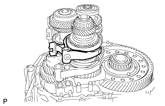
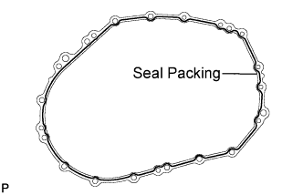
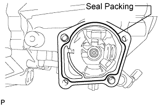
| 36. INSTALL MANUAL TRANSMISSION CASE |
Apply seal packing to the transmission case, as shown in the illustration.
- Seal packing:
- Toyota Genuine Seal Packing Black, Three Bond 1207B or Equivalent
- NOTICE:
- Assemble parts within 10 minutes of application. Otherwise, the packing (Toyota Genuine Seal Packing) material must be removed and reapplied.
 |
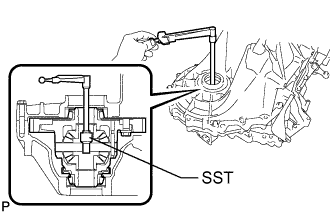
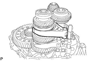
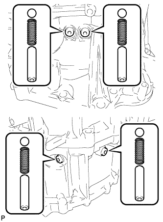
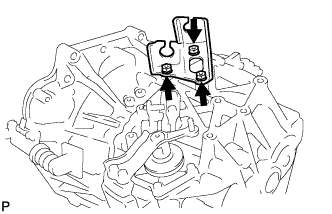
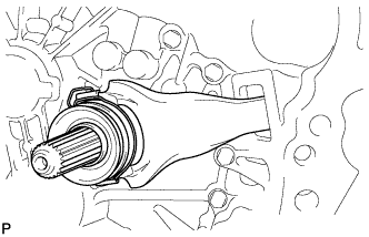
Use 2 snap ring pliers to keep the snap ring stretched and install the transmission case.
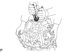 |
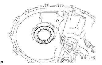
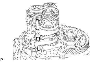
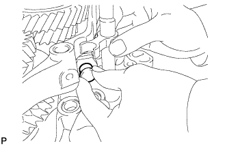
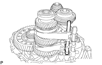
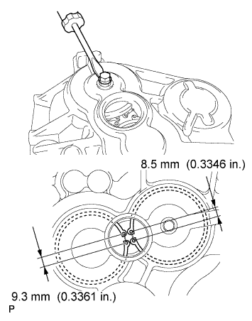
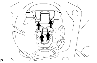
Install a bolt to the No. 1 output shaft and lift the No. 1 output shaft from the service hole. Make sure that the snap rings are positioned correctly in the bearing grooves by checking that the distances between the centers of the snap ring holes are as shown in the illustration.
 |
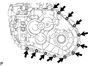
Install the transmission case to the front transaxle case with the 12 bolts.
- Torque:
- 29 N*m{ 299 kgf*cm , 22 ft.*lbf }
|
Install the transmission case to the front transaxle case with the 6 bolts.
- Torque:
- 29 N*m{ 299 kgf*cm , 22 ft.*lbf }
|
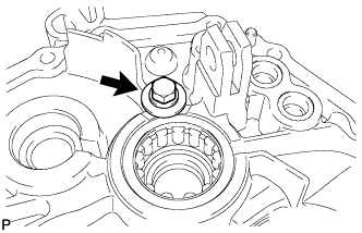
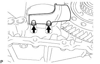
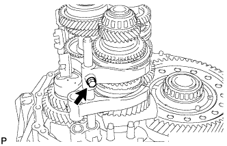
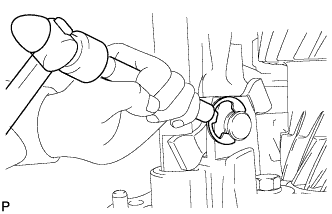
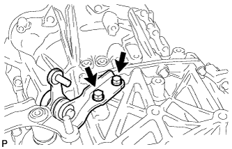
| 37. INSTALL REVERSE IDLER GEAR SHAFT BOLT |
Coat the shaft bolt with adhesive, and install it and a new gasket.
- Adhesive:
- Toyota Genuine Adhesive 1344, Three Bond 1344 or Equivalent
- Torque:
- 80 N*m{ 816 kgf*cm , 59 ft.*lbf }
 |
| 38. INSTALL SHIFT DETENT BALL |
Coat the plugs with adhesive.
- Adhesive:
- Toyota Genuine Adhesive 1344, Three Bond 1344 or Equivalent
 |
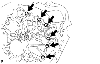
Using a 6 mm hexagon wrench, install the 4 balls, 4 spring seats and 4 plugs.
- Torque:
- 22 N*m{ 228 kgf*cm , 17 ft.*lbf }
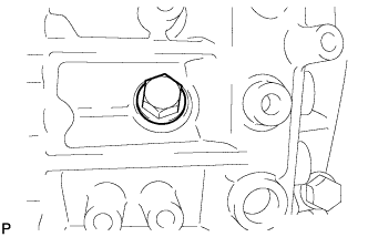
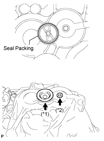
| 39. INSTALL MANUAL TRANSMISSION CASE PLUG |
Apply seal packing black to the transmission case, as shown in the illustration.
- Seal packing:
- Toyota Genuine Seal Packing, Three Bond 1207B or Equivalent
 |
Coat the transmission case plug with adhesive.
- Adhesive:
- Toyota Genuine Adhesive 1344, Three Bond 1344 or Equivalent
Install the transmission case plug into the transmission case.
- Torque:
- 55 N*m{ 561 kgf*cm , 41 ft.*lbf } for case plug *1
- 22 N*m{ 228 kgf*cm , 17 ft.*lbf } for case plug *2
| 40. INSTALL O-RING |
Coat the O-ring with the grease, and install it into the shift and select pin.
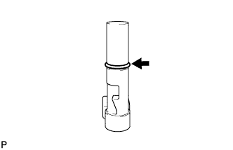 |
| 41. INSTALL SHIFT AND SELECT PIN |
Install the spring.
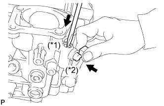 |
While pressing the shift and select pin (*1) in as much as possible, push in the shift and select pin (*2).
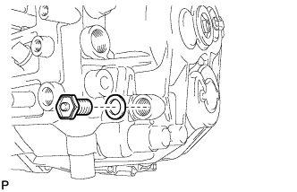
| 42. INSTALL MANUAL TRANSMISSION FILLER PLUG |
Install a new gasket and the filler plug.
- Torque:
- 39 N*m{ 400 kgf*cm , 29 ft.*lbf }
 |
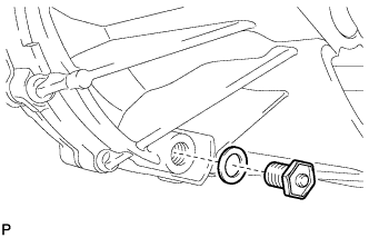
| 43. INSTALL DRAIN PLUG |
Install a new gasket and the drain plug.
- Torque:
- 39 N*m{ 400 kgf*cm , 29 ft.*lbf }
 |
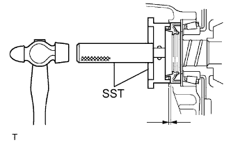
| 44. INSTALL TRANSMISSION CASE OIL SEAL |
Coat the lip of a new oil seal with MP grease.
Using SST and a hammer, tap in the seal.
- Standard depth:
- -0.5 to 0.5 mm (-0.012 to 0.012 in.)
- NOTICE:
- Do not damage the lip of the oil seal.
 |
| 45. INSTALL TRANSAXLE CASE OIL SEAL |
Coat the lip of a new oil seal with MP grease.
Using SST and a hammer, install the oil seal.
- Standard depth:
- -0.5 to 0.5 mm (-0.012 to 0.012 in.)
- NOTICE:
- Do not damage the lip of the oil seal.
 |
| 46. INSTALL CONTROL SHAFT COVER |
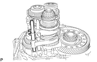
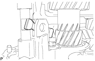
Align the 4 shift fork shafts as shown in the illustration.
 |
Apply seal packing black to the transmission case, as shown in the illustration.
- Seal packing:
- Toyota Genuine Seal Packing, Three Bond 1207B or Equivalent
 |
Coat the 4 bolts with adhesive.
- Adhesive:
- Toyota Genuine Adhesive 1344, Three Bond 1344 or Equivalent
Install the shift and select lever shaft onto the transmission case with the 4 bolts.
- Torque:
- 19 N*m{ 190 kgf*cm , 14 ft.*lbf }
 |
| 47. INSTALL SHIFT GATE PIN |
Coat the shift gate pin with sealant.
- Adhesive:
- Toyota Genuine Adhesive 1344, Three Bond 1344, or equivalent
 |
Install the shift gate pin onto the manual transmission case.
- Torque:
- 30 N*m{ 306 kgf*cm , 22 ft.*lbf }
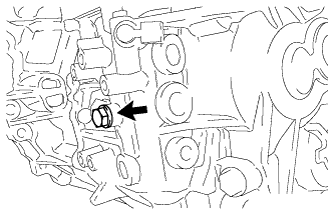
| 48. INSTALL NO. 2 LOCK BALL ASSEMBLY |
Coat the lock ball with sealant.
- Adhesive:
- Toyota Genuine Adhesive 1344, THREE BOND 1344 or equivalent
 |
Install the lock ball onto the transmission case.
- Torque:
- 29 N*m{ 299 kgf*cm , 22 ft.*lbf }
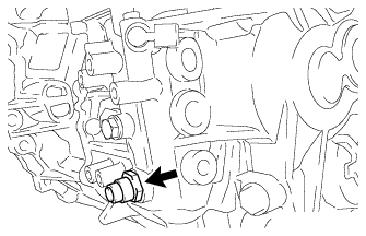
| 49. INSTALL NO. 1 LOCK BALL ASSEMBLY |
Coat the lock ball with sealant.
- Adhesive:
- Toyota Genuine Adhesive 1344, THREE BOND 1344 or Equivalent
 |
Install the lock ball onto the transmission case.
- Torque:
- 39 N*m{ 400 kgf*cm , 29 ft.*lbf }
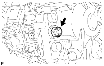
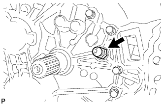
| 50. INSTALL BACK-UP LIGHT SWITCH ASSEMBLY |
Install the back-up light switch onto the transmission case.
- SST
- 09816-30010
- Torque:
- 40 N*m{ 410 kgf*cm , 30 ft.*lbf }
 |
| 51. INSTALL SELECTING BELL CRANK ASSEMBLY |
Coat the 2 bolts with sealant, and install the selecting bell crank to the transmission case with the bolts.
- Sealant:
- Toyota genuine adhesive 1344, THREE BOND 1344, LOCTITE 242 or equivalent
- Torque:
- 20 N*m{ 204 kgf*cm , 15 ft.*lbf }
 |
| 52. INSTALL FLOOR SHIFT CONTROL LEVER HOUSING SUPPORT BRACKET |
Install the floor shift control lever housing support bracket onto the transaxle case with the 3 bolts.
- Torque:
- 17 N*m{ 173 kgf*cm , 13 ft.*lbf }
 |
| 53. INSTALL CLUTCH RELEASE FORK BOOT |
Install the clutch release fork boot onto the transmission case.
 |
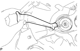
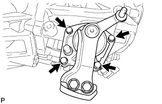
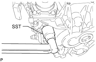
| 54. INSTALL RELEASE FORK SUPPORT |
Using a deep socket wrench, install the release fork support to the front transaxle case.
- Torque:
- 37 N*m{ 375 kgf*cm , 27 ft.*lbf }
 |
| 55. INSTALL CLUTCH RELEASE BEARING ASSEMBLY |
Apply release hub grease to the following areas
- The contact surface of the release fork and release bearing.
- The contact surface of the release fork and push rod.
- The pivot points of the release fork.
- Release hub grease:
- Part No. 08887-01806, RELEASE HUB GREASE or equivalent
- The contact surface of the release fork and release bearing.
 |
Apply clutch sealant grease to the spline coupling part.
- Clutch spline grease:
- Part No. 08887-01706, CLUTCH SPLINE GREASE or equivalent
| 56. INSTALL CLUTCH RELEASE FORK SUB-ASSEMBLY |
Install the bearing to the release fork, and then install them to the transaxle.
 |