DTC P0504 Brake Switch "A" / "B" Correlation |

for Preparation Click here
DESCRIPTION
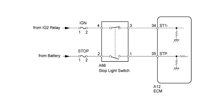
The stop light switch is a duplex system that transmits two signals: STP and ST1-. These two signals are used by the ECM to monitor whether or not the brake system is working properly. If the signals, which indicate that the brake pedal is being depressed and released, are detected simultaneously, the ECM interprets this as a malfunction in the stop light switch and sets the DTC.- HINT:
- The normal conditions are as shown in the table below. The signals can be read using the intelligent tester.
| Signals | Brake Pedal Released | In Transition | Brake Pedal Depressed |
| STP | OFF | ON | ON |
| ST1- | ON | ON | OFF |
| DTC Detection Drive Pattern | DTC Detection Condition | Trouble Area |
| Release and depress brake pedal with ignition switch ON | Conditions (a), (b) and (c) continue for 0.5 seconds or more (1 trip detection logic): (a) Ignition switch ON. (b) Brake pedal is released. (c) The STP signal is off when the ST1- signal is off, or the STP signal is on when the ST1- signal is on. |
|
| DTC No. | Data List |
| P0504 | Stop Light Switch |
WIRING DIAGRAM
INSPECTION PROCEDURE
- HINT:
- Read freeze frame data using the intelligent tester. Freeze frame data records the engine condition when malfunctions are detected. When troubleshooting, freeze frame data can help determine if the vehicle was moving or stationary, if the engine was warmed up or not, and other data from the time the malfunction occurred.
- Stop light switch conditions can be checked using the intelligent tester.
- Connect the intelligent tester to the DLC3.
- Turn the ignition switch to ON.
- Turn the tester on.
- Enter the following menus: Powertrain / Engine and ECT / Data List / Stop Light Switch.
- Check Stop Light Switch when the brake pedal is depressed and released.
| Brake Pedal Operation | Specified Condition |
| Depressed | ON |
| Released | OFF |
- NOTICE:
- Inspect the fuses of circuits related to this system before performing the following inspection procedure.
- After replacing the ECM, the new ECM needs registration (Click here) and initialization (Click here).
| 1.CHECK STOP LIGHT SWITCH ASSEMBLY (TERMINAL B VOLTAGE) |
Disconnect the stop light switch connector.
 |
Measure the voltage according to the value(s) in the table below.
- Standard Voltage:
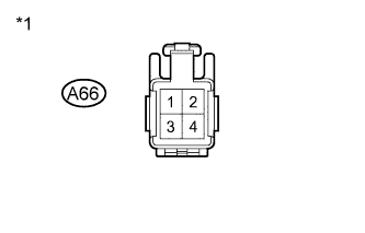
Tester Connection Switch Condition Specified Condition A66-2 - Body ground Always 11 to 14 V A66-4 - Body ground Ignition switch ON 11 to 14 V
Text in Illustration *1 Front view of wire harness connector
(to Stop Light Switch)
Reconnect the stop light switch connector.
|
| ||||
| OK | |
| 2.INSPECT STOP LIGHT SWITCH ASSEMBLY |
 |
Remove the stop light switch.
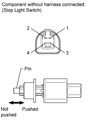
Measure the resistance according to the value(s) in the table below.
- Standard Resistance:
Tester Connection Switch Condition Specified Condition 1 - 2 Switch pin not pushed Below 1 Ω Switch pin pushed 10 kΩ or higher 3 - 4 Switch pin not pushed 10 kΩ or higher Switch pin pushed Below 1 Ω
Reinstall the stop light switch.
|
| ||||
| OK | |
| 3.CHECK ECM (STP AND ST1- VOLTAGE) |
 |
Disconnect the ECM connector.
Turn the ignition switch to ON.
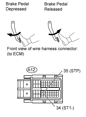
Measure the voltage according to the value(s) in the table below.
- Standard Voltage:
Tester Connection Brake Pedal Condition Specified Condition A12-34 (ST1-) - Body ground Released 11 to 14 V Depressed 0 to 3 V A12-35 (STP) - Body ground Released 0 to 3 V Depressed 11 to 14 V
Reconnect the ECM connector.
|
| ||||
|
| ||||
| 4.REPLACE STOP LIGHT SWITCH ASSEMBLY |
Replace the stop light switch assembly (Click here).
|
| ||||
| 5.REPLACE ECM |
Replace the ECM (Click here).
|
| ||||
| 6.REPAIR OR REPLACE HARNESS OR CONNECTOR |
Repair or replace the harness or connector.
| NEXT | |
| 7.CONFIRM WHETHER MALFUNCTION HAS BEEN SUCCESSFULLY REPAIRED |
Connect the intelligent tester to the DLC3.
Clear the DTCs (Click here).
Turn the ignition switch off.
Turn the ignition switch to ON and turn the tester on.
Release and depress the brake pedal.
Enter the following menus: Powertrain / Engine and ECT / DTC.
Confirm that the DTC is not output again.
| NEXT | ||
| ||