AUDIO AND VISUAL SYSTEM (for Radio Receiver Type) > Speed Signal Circuit |

for Preparation Click here
DESCRIPTION
This circuit is necessary for the ASL (Auto Sound Levelizer) built into the radio receiver assembly. Speed signals are received from the combination meter and used for the ASL.The ASL function automatically adjusts the sound data in order to enable the listener to hear the sound of the audio system clearly even when vehicle noise increases (as vehicle noise increases, the volume is turned up, etc.).
- HINT:
- A voltage of 12 V or 5 V is output from each ECU and then input to the combination meter. The signal is changed to a pulse signal at the transistor in the combination meter. Each ECU controls its respective system based on the pulse signal.
- If a short occurs in any of the ECUs or in the wire harness connected to an ECU, both systems in the diagram below will not operate normally.
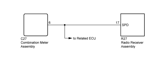
WIRING DIAGRAM
INSPECTION PROCEDURE
| 1.CHECK OPERATION OF SPEEDOMETER |
Drive the vehicle and check if the function of the speedometer in the combination meter is normal.
- OK:
- Actual vehicle speed and the speed indicated on the speedometer are the same.
- HINT:
- The vehicle speed sensor is functioning normally when the indication on the speedometer is normal.
|
| ||||
| OK | |
| 2.CHECK HARNESS AND CONNECTOR (RADIO RECEIVER ASSEMBLY - COMBINATION METER ASSEMBLY) |
Disconnect the R27 radio receiver assembly connector.
Disconnect the C27 combination meter assembly connector.
Measure the resistance according to the value(s) in the table below.
- Standard Resistance:
Tester Connection Condition Specified Condition R27-17 (SPD) - C27-6 Always Below 1 Ω R27-17 (SPD) - Body ground Always 10 kΩ or higher
|
| ||||
| OK | ||
| ||