RADIATOR > REASSEMBLY |

for Preparation Click here
| 1. INSTALL OIL COOLER ASSEMBLY (for Automatic Transmission) |
Install 2 new O-rings to the oil cooler.
 |
Install the oil cooler to the tank lower with the 2 lock plates and 2 nuts.
- Torque:
- 14.7 N*m{ 150 kgf*cm , 11 ft.*lbf }
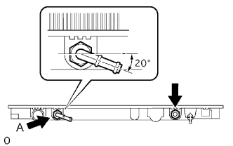
Install the 2 cooler pipes.
- Torque:
- 8.34 N*m{ 85 kgf*cm , 74 in.*lbf }
- HINT:
- Set the cooler pipe labeled A to the location and angle shown in the illustration.
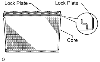
| 2. INSPECT LOCK PLATE FOR DAMAGE |
Inspect the lock plate for damage.
If the sides of the lock plate groove are deformed, reassembly of the tank will be impossible. Correct any deformations with pliers.
Water will leak if the bottom of the lock plate groove is damaged or dented. Repair or replace it as necessary.- NOTICE:
- The radiator can only be recaulked twice. After the second time, the radiator core must be replaced.
 |
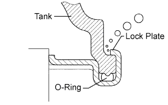
| 3. INSTALL RADIATOR TANK UPPER AND TANK LOWER |
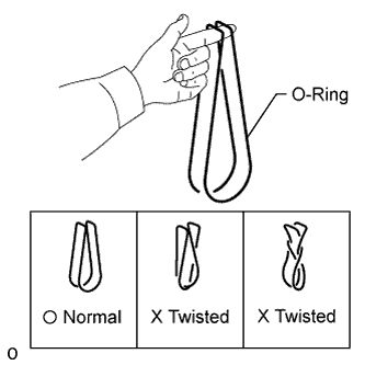
Check that there are no foreign objects in the lock plate groove, and install a new O-ring. Make sure the O-ring is not twisted.
- HINT:
- When cleaning the lock plate groove, lightly rub it with sandpaper without scratching it.
 |
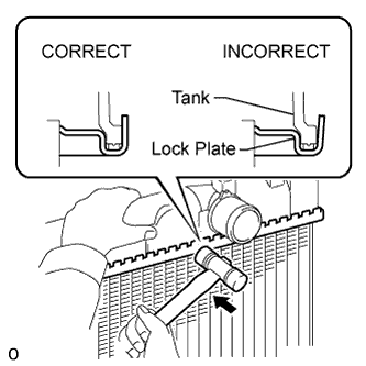
Install the tank without damaging the O-ring.
Tap the lock plate with a plastic-faced hammer so that there is no gap between the lock plate and the tank.
 |
| 4. ASSEMBLE SST |
Install the punch assembly to part A of the overhaul handle as shown in the illustration.
- SST
- 09230-01010
(09231-01010, 09231-01020)
09231-14010
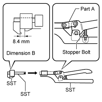 |
While squeezing the handle, adjust the stopper bolt so that dimension B is as specified below.
- Dimension B:
- 8.4 mm (0.331 in.)
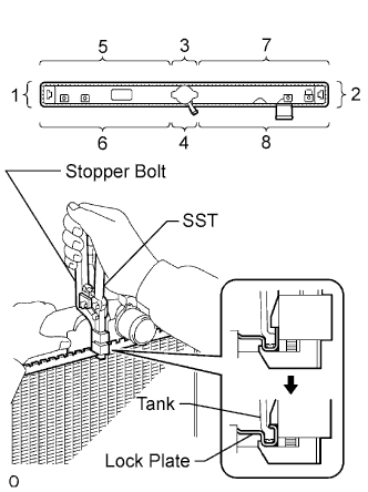
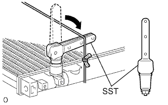
| 5. CAULK LOCK PLATE |
Lightly press SST against the lock plate in the order shown in the illustration. After repeating this a few times, fully caulk the lock plate by squeezing the handle until stopped by the stopper bolt.
- SST
- 09230-01010
(09231-01010, 09231-01020)
09231-14010
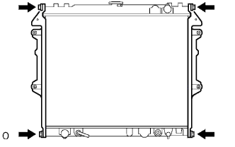
- NOTICE:
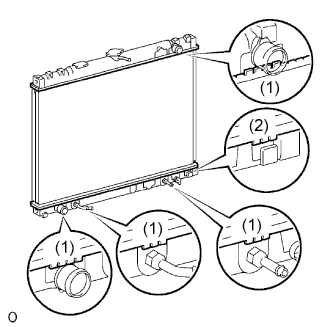
- Do not press the protruding areas around the ports (1) and bracket (2).
Do not use SST to press the areas indicated by the circle marks in the illustration. Use pliers and be careful not to damage the core plates.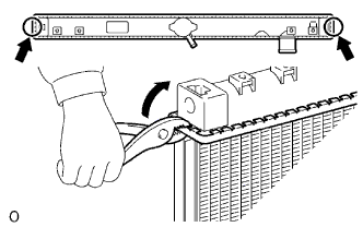
 |
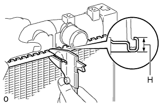
Check the lock plate height H after completing the caulking.
- Standard plate height H:
- 8.8 mm (0.346 in.)
 |
| 6. INSTALL RADIATOR DRAIN COCK PLUG |
Install a new O-ring to the drain cock plug.
Install the drain cock plug.
| 7. INSPECT FOR WATER LEAKS |
Plug the inlet and outlet pipes of the radiator with SST.
- SST
- 09230-01010
(09231-00030, 09231-00060)
 |
Using a radiator cap tester, apply pressure to the radiator.
- Standard test pressure:
- 177 kPa (1.8 kgf/cm2, 26 psi)
Submerge the radiator in water.
Inspect for leaks.
- HINT:
- For radiators with resin tanks, there is clearance between the tank and lock plate where a small amount of air will remain. This air is released when the radiator is submerged in water, giving the appearance of an air leak. Before performing the water leak test, first shake the radiator in the water until all air bubbles are released.
 |
| 8. INSTALL RADIATOR BRACKET SUB-ASSEMBLY |
Install the 2 brackets with the 4 bolts.
- Torque:
- 13 N*m{ 133 kgf*cm , 10 ft.*lbf }
 |