DTC C0273/13 Open in ABS Motor Relay Circuit |
DTC C0274/14 Short to B+ in ABS Motor Relay Circuit |

for Preparation Click here
DESCRIPTION
The ABS motor relay supplies power to the ABS pump motor. While the ABS is activated, the ECU turns the motor relay ON and operates the ABS pump motor.| DTC No. | DTC Detection Condition | Trouble Area |
| C0273/13 | When either of following is detected: 1. Both conditions continue for at least 0.2 seconds
|
|
| C0274/14 | Relay contact is closed when relay is OFF for at least 4 seconds |
|
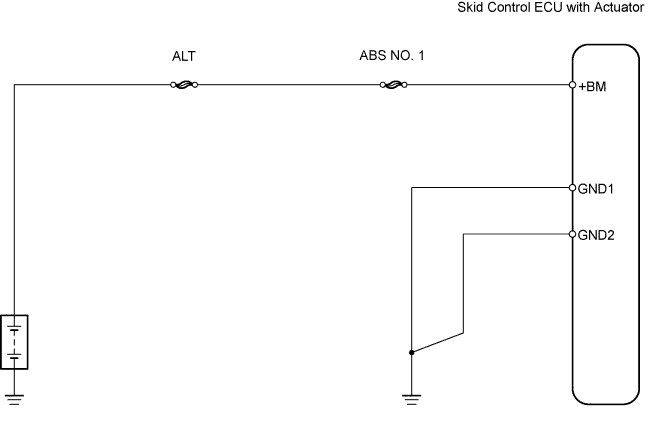
WIRING DIAGRAM
INSPECTION PROCEDURE
| 1.CHOOSE DIAGNOSIS METHOD |
Choose the diagnosis method.
Method Method Proceed to Using intelligent tester A Not using intelligent tester B
|
| ||||
| A | |
| 2.PERFORM ACTIVE TEST BY INTELLIGENT TESTER (ABS MOTOR RELAY) |
Select the Active Test, generate a control command, and then check that the ABS motor relay operates.
Skid control ECU Item Vehicle Condition / Test Details Diagnostic Note ABS Motor Relay Turns ABS motor relay ON / OFF Operation sound of motor can be heard - OK:
- Operation sound of ABS motor is heard.
|
| ||||
| OK | |
| 3.INSPECT SKID CONTROL ECU CONNECTOR |
Check the ECU connector's connecting condition.
- OK:
- Connector is securely connected.
|
| ||||
| OK | |
| 4.RECONFIRM DTC |
- HINT:
- These codes are output when a problem is detected in the brake actuator assembly.
- As the ABS motor relay is built into the brake actuator assembly, ABS motor relay and solenoid unit inspection cannot be performed.
- Be sure to check if the DTC is output before replacing the brake actuator assembly.
Clear the DTCs.
Drive the vehicle at 6 km/h (4 mph) or more.
Check for DTCs.
Result Result Proceed to DTC is output A DTC is not output B
|
| ||||
| A | ||
| ||
| 5.INSPECT FUSE (ALT, ABS NO. 1) |
Remove the ALT and ABS NO. 1 H-fuses from the engine room junction block.
Measure the resistance of the H-fuses.
- Standard resistance:
- Below 1 Ω
|
| ||||
| OK | |
| 6.CHECK WIRE HARNESS (SKID CONTROL ECU - BATTERY AND BODY GROUND) |
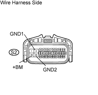 |
Disconnect the S2 ECU connector.
Measure the voltage of the wire harness side connector.
- Standard voltage:
Tester Connection Specified Condition S2-23 (+BM) - Body ground 10 to 14 V
Measure the resistance of the wire harness side connector.
- Standard resistance:
Tester Connection Specified Condition S2-2 (GND1) - Body ground Below 1 Ω S2-24 (GND2) - Body ground Below 1 Ω
|
| ||||
| OK | |
| 7.RECONFIRM DTC |
- HINT:
- These codes are output when a problem is detected in the brake actuator assembly.
- As the ABS motor relay is built into the brake actuator assembly, ABS motor relay and solenoid unit inspection cannot be performed.
- Be sure to check if the DTC is output before replacing the brake actuator assembly.
Clear the DTCs.
Drive the vehicle at 6 km/h (4 mph) or more.
Check for DTCs.
Result Result Proceed to DTC is output A DTC is not output B
|
| ||||
| A | ||
| ||