FLOOR SHIFT ASSEMBLY > INSTALLATION |

for Preparation Click here
| 1. INSTALL FLOOR SHIFT ASSEMBLY |
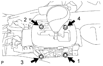 |
Install the floor shift with the 4 bolts.
- Torque:
- 14 N*m{ 143 kgf*cm , 10 ft.*lbf }
- NOTICE:
- Tighten the bolts in the order shown in the illustration.
Connect the clamp and 2 connectors.
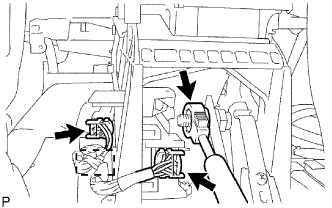 |
Move the shift lever to L.
Connect the transmission control cable.
| 2. CONNECT CABLE TO NEGATIVE BATTERY TERMINAL |
| 3. PERFORM INITIALIZATION |
Perform initialization (Click here).
- NOTICE:
- Certain systems need to be initialized after disconnecting and reconnecting the cable from the negative (-) battery terminal.
| 4. ADJUST SHIFT LEVER POSITION |
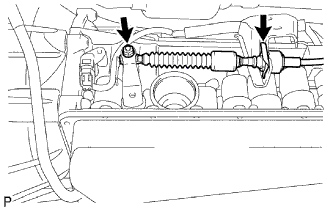 |
Remove the nut and disconnect the control cable.
Remove the clip and disconnect the control cable from the control cable bracket.
Push the control shaft rearward as much as possible.
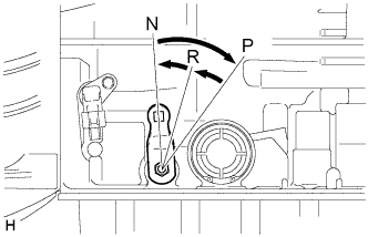 |
Return the control shaft lever 2 notches to the N position.
While holding the control shaft lever slightly toward the R position side, tighten the nut.
- Torque:
- 14 N*m{ 143 kgf*cm , 10 ft.*lbf }
| 5. INSPECT SHIFT LEVER POSITION |
When moving the shift lever from P to R with the ignition switch ON and the brake pedal depressed, make sure that the shift lever moves smoothly and correctly into position.
Start the engine and make sure that the vehicle moves forward after moving the shift lever from N to D, and moves rearward after shifting to the.
If the results are not as specified, inspect the park/neutral position switch and check the shift lever.
| 6. INSTALL CONSOLE BOX ASSEMBLY |
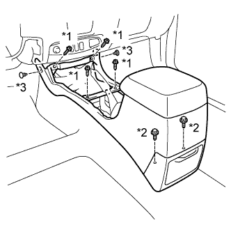 |
Install the console box with the 4 screws and 2 bolts.
Install the 2 clips.
Text in Illustration *1 Screw *2 Bolt *3 Clip
| 7. INSTALL UPPER CONSOLE PANEL SUB-ASSEMBLY |
Attach the 12 claws to install the upper console panel.
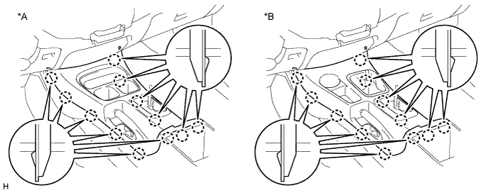
Text in Illustration *A for 2WD *B for 4WD
| 8. INSTALL PARKING BRAKE HOLE COVER SUB-ASSEMBLY |
Attach the 4 claws to install the parking brake hole cover.