DTC C1249/49 Open in Stop Light Switch Circuit |

for Preparation Click here
DESCRIPTION
This circuit recognizes brake operation by sending a stop light signal to the skid control ECU.| DTC No. | DTC Detection Condition | Trouble Area |
| C1249/49 | Both conditions continue for at least 0.3 seconds:
|
|
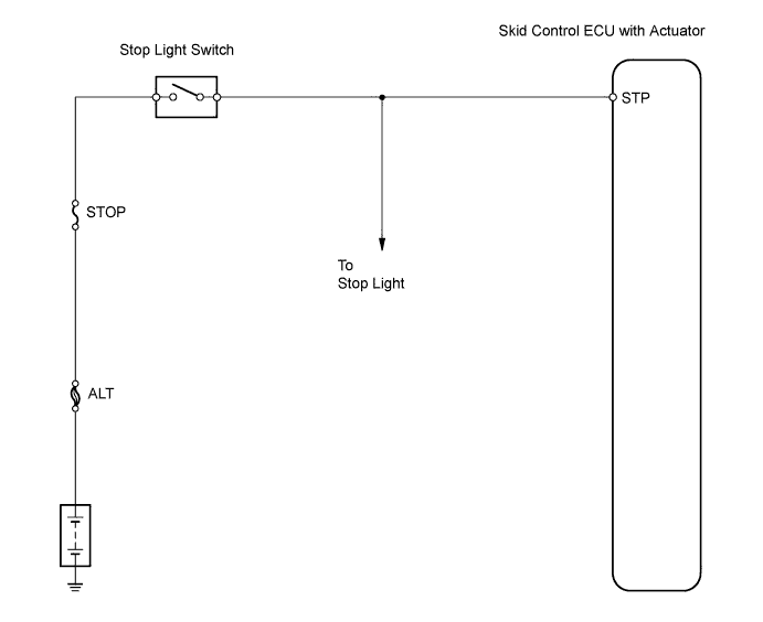
WIRING DIAGRAM
INSPECTION PROCEDURE
| 1.CHECK STOP LIGHT SWITCH (OPERATION) |
Check that the stop light illuminates when the brake pedal is depressed, and turns off when the brake pedal is released.
- OK:
Condition Stop Light Condition Brake pedal depressed Illuminates Brake pedal released Turns off
|
| ||||
| OK | |
| 2.CHECK WIRE HARNESS (SKID CONTROL ECU - STOP LIGHT SWITCH) |
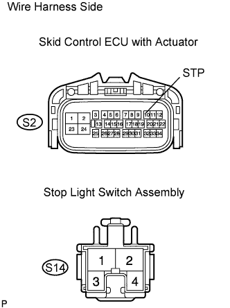 |
Disconnect the S2 ECU connector.
Disconnect the S14 stop light switch connector.
Measure the resistance of the wire harness side connectors.
- Standard resistance:
Tester Connection Specified Condition S2-10 (STP) - S14-1 Below 1 Ω
|
| ||||
| OK | |
| 3.CHECK IF DTC OUTPUT RECURS |
Clear the DTCs.
Drive the vehicle at approximately 30 km/h (19 mph) or more for 60 seconds or more.
Check for DTCs.
Result Result Proceed to DTC is output A DTC is not output B
|
| ||||
| A | ||
| ||
| 4.INSPECT STOP LIGHT SWITCH ASSEMBLY |
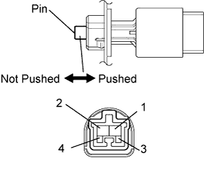 |
Disconnect the switch connector.
Measure the resistance of the stop light switch.
- Standard resistance:
Tester Connection Switch Condition Specified Condition 1 - 2 Pin not pushed Below 1 Ω 1 - 2 Pin pushed 10 kΩ or higher 3 - 4 Pin not pushed 10 kΩ or higher 3 - 4 Pin pushed Below 1 Ω
|
| ||||
| OK | |
| 5.CHECK WIRE HARNESS (SKID CONTROL ECU - BATTERY) |
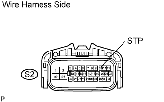 |
Disconnect the S2 ECU connector.
Measure the voltage of the wire harness side connector.
- Standard voltage:
Tester Connection Condition Specified Condition S2-10 (STP) - Body ground Brake pedal depressed 8 to 14 V S2-10 (STP) - Body ground Brake pedal released Below 1 V
|
| ||||
| OK | |
| 6.CHECK IF DTC OUTPUT RECURS |
Clear the DTCs.
Drive the vehicle at approximately 30 km/h (19 mph) or more for 60 seconds or more.
Check for DTCs.
Result Result Proceed to DTC is output A DTC is not output B
|
| ||||
| A | ||
| ||