SFI SYSTEM (w/o Secondary Air Injection System) > ECM Power Source Circuit |

for Preparation Click here
DESCRIPTION
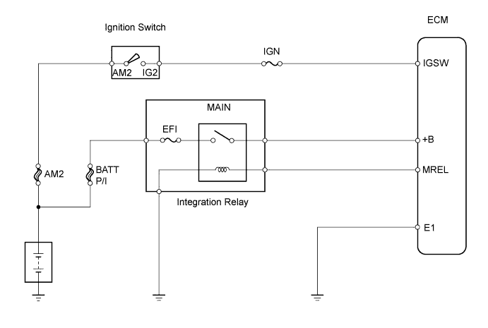
When the ignition switch is turned ON, the battery voltage is applied to terminal IGSW of the ECM. The ECM "MREL" output signal causes a current to flow to the MAIN relay coil, closing the contacts of the MAIN relay and supplying power to terminal +B of the ECM.WIRING DIAGRAM
INSPECTION PROCEDURE
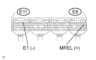
| 1.CHECK ECM (+B VOLTAGE) |
 |
Turn the ignition switch ON.
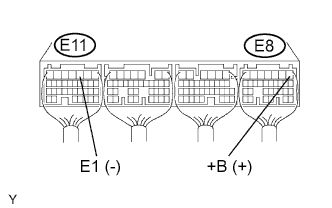
Measure the voltage of the ECM connectors.
- Standard voltage:
Tester Connection Specified Condition E8-1 (+B) - E11-3 (E1) 9 to 14 V
|
| ||||
| NG | |
| 2.CHECK WIRE HARNESS (ECM - BODY GROUND) |
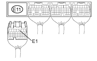 |
Disconnect the E11 ECM connector.
Measure the resistance of the wire harness side connector.
- Standard resistance:
Tester Connection Specified Condition E11-3 (E1) - Body ground Below 1 Ω
|
| ||||
| OK | |
| 3.CHECK ECM (IGSW VOLTAGE) |
 |
Turn the ignition switch ON.
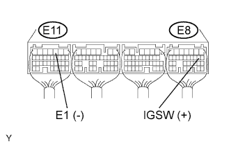
Measure the voltage of the ECM connectors.
- Standard voltage:
Tester Connection Specified Condition E8-9 (IGSW) - E11-3 (E1) 9 to 14 V
|
| ||||
| NG | |
| 4.INSPECT FUSE (IGN) |
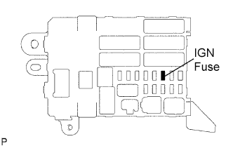 |
Remove the IGN fuse from the instrument panel junction block.
Measure the resistance of the fuse.
- Standard:
- Below 1 Ω
|
| ||||
| OK | |
| 5.INSPECT IGNITION SWITCH ASSEMBLY |
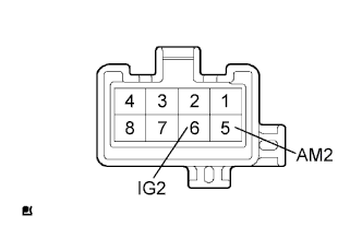 |
Disconnect the I8 ignition switch connector.
Measure the resistance of the switch.
- Standard resistance:
Tester Connection Switch Condition Specified Condition 5 (AM2) - 6 (IG2) LOCK 10 kΩ or higher 5 (AM2) - 6 (IG2) ON Below 1 Ω
|
| ||||
| OK | ||
| ||
| 6.CHECK ECM (MREL VOLTAGE) |
 |
Turn the ignition switch ON.
Measure the voltage of the ECM connectors.
- Standard voltage:
Tester Connection Specified Condition E8-8 (MREL) - E11-3 (E1) 9 to 14 V
|
| ||||
| OK | |
| 7.INSPECT FUSE (EFI) |
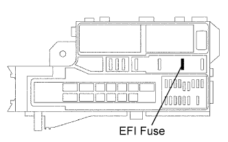 |
Remove the EFI fuse from the engine room junction block.
Measure the resistance of the fuse.
- Standard resistance:
- Below 1 Ω
|
| ||||
| OK | |
| 8.CHECK INTEGRATION NO.1 RELAY (MAIN RELAY) |
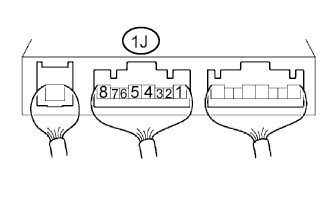 |
Remove the integration relay from the engine room junction block.
Measure the voltage of the MAIN relay.
- Standard voltage:
Tester Connection Condition Specified Condition 1J-4 - Body ground Ignition switch ON 10 to 14 V
|
| ||||
| OK | |
| 9.CHECK WIRE HARNESS (INTEGRATION RELAY (MAIN RELAY) - ECM, BODY GROUND) |
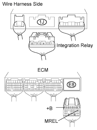 |
Remove the integration relay from the engine room junction block.
Disconnect the 1J integration relay connector.
Disconnect the E8 ECM connector.
Measure the resistance of the wire harness side connectors.
- Standard resistance:
Tester Connection Specified Condition 1J-2 - E8-8 (MREL) Below 1 Ω 1J-4 - E8-1 (+B) Below 1 Ω 1J-3 - Body ground Below 1 Ω 1J-2 or E8-8 (MREL) - Body ground 10 kΩ or higher 1J-4 or E8-1 (+B) - Body ground 10 kΩ or higher
|
| ||||
| OK | ||
| ||