OIL PUMP > REMOVAL |

for Preparation Click here
| 1. DISCHARGE FUEL SYSTEM PRESSURE |
- CAUTION:
- Do not disconnect any part of the fuel system until you have discharged the fuel system pressure.
- Even after discharging the fuel pressure, place a cloth or equivalent over fittings as you separate them to reduce the risk of fuel spray on yourself or in the engine compartment.
Disconnect the cable from the negative (-) battery terminal.
- CAUTION:
- Wait at least 90 seconds after disconnecting the cable from the negative (-) battery terminal to prevent airbag and seat belt pretensioner activation.
Remove the front driver side scuff plate.
Using a screwdriver, detach the 7 claws.
- HINT:
- Tape the screwdriver tip before use.
Using a clip remover, detach the 3 clips and remove the scuff plate.
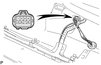
Turn up the floor carpet and disconnect the joining connector, as shown in the illustration.
- HINT:
- This connector has the lines of the fuel pump and rear speed sensor.
 |
Connect the cable to the negative (-) battery terminal.
Start the engine. After the engine has stopped on its own, turn the ignition switch OFF.
- HINT:
- DTC C0210/33 and DTC C0215/34 (rear speed sensor circuit) and DTC P0171/25 (system too lean) may be set.
Crank the engine again, and then check that the engine does not start.
Loosen the fuel tank cap, and then discharge the pressure in the fuel tank completely.
Connect the fuel pump connector.
Install the front driver side scuff plate.
Clear the DTCs (Click here).
| 2. DISCONNECT CABLE FROM NEGATIVE BATTERY TERMINAL |
- CAUTION:
- Wait at least 90 seconds after disconnecting the cable from the negative (-) battery terminal to prevent airbag and seat belt pretensioner activation.
| 3. REMOVE ENGINE ASSEMBLY |
Remove the engine from the vehicle (Click here).
| 4. INSTALL ENGINE TO STAND |
Place the engine onto the stand.
| 5. REMOVE IGNITION COIL |
Remove the bolt and ignition coil.
| 6. REMOVE SPARK PLUG |
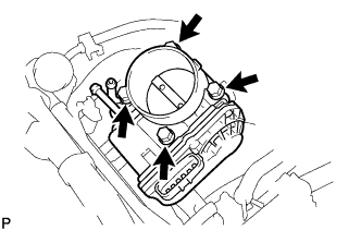
| 7. REMOVE THROTTLE BODY |
Disconnect the throttle position sensor and control motor connector.
Disconnect the 2 water by-pass hoses.
Remove the 4 bolts and throttle body.
 |
Remove the gasket.
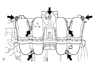
| 8. REMOVE INTAKE MANIFOLD |
Disconnect the crankshaft position sensor from the clamp.
Remove the 5 bolts, 2 nuts, intake manifold and gasket.
 |
| 9. REMOVE GENERATOR |
Detach the terminal cap.
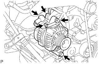 |
Remove the nut, bolt and generator wire.
Disconnect the generator connector.
Remove the 2 bolts and generator.
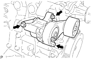
| 10. REMOVE COMPRESSOR MOUNTING BRACKET |
Remove the 5 bolts and compressor mounting bracket.
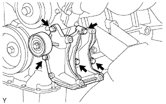 |
| 11. REMOVE V-RIBBED BELT TENSIONER |
Remove the 3 bolts and belt tensioner.
 |
| 12. REMOVE WATER INLET |
Remove the bolt, 2 nuts, water inlet and gasket.
| 13. REMOVE THERMOSTAT |
Remove the thermostat and gasket.
| 14. REMOVE IDLER PULLEY |
Remove the bolt, pulley plate, idler pulley and spacer.
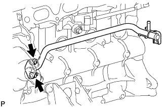
| 15. REMOVE NO. 1 WATER BY-PASS PIPE |
Remove the 2 nuts, water by-pass pipe and gasket.
 |
| 16. REMOVE OIL FILLER CAP |
| 17. REMOVE CYLINDER HEAD COVER |
Remove the 19 bolts, 2 nuts, head cover and 2 gaskets.
| 18. REMOVE CAMSHAFT POSITION SENSOR |
Disconnect the sensor connector.
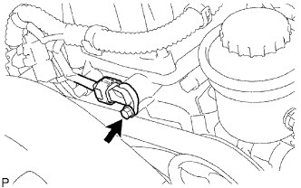 |
Remove the bolt and sensor.
| 19. REMOVE CRANKSHAFT PULLEY |
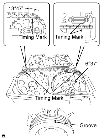
Turn the crankshaft pulley, and align its groove with timing mark 0 of the timing chain cover.
Check that the timing marks of the camshaft timing gear and sprocket are aligned with the timing marks of the No. 1 bearing cap, as shown in the illustration.
 |
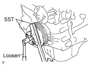
Using SST, hold the crankshaft pulley and loosen the pulley set bolt.
- SST
- 09213-54015
(91651-60855)
09330-00021
 |
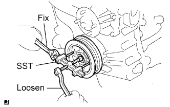
Using the pulley set bolt and SST, remove the crankshaft pulley.
- SST
- 09950-50013
(09951-05010, 09952-05010, 09953-05010, 09954-05021)
 |
| 20. REMOVE NO. 2 OIL PAN |
Remove the drain plug and gasket.
Remove the 20 bolts and 2 nuts.
Insert the blade of oil pan seal cutter between the oil pans. Cut through the applied sealer and remove the oil pan.
- NOTICE:
- Be careful not to damage the contact surfaces of the oil pans.
 |
| 21. REMOVE OIL STRAINER |
Remove the bolt, 2 nuts, oil strainer and gasket.
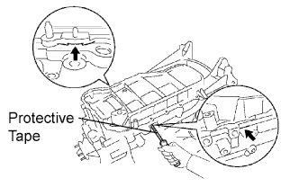
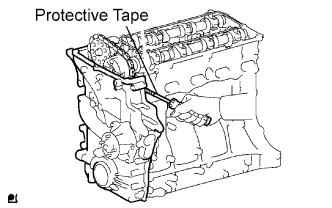
| 22. REMOVE NO. 1 OIL PAN |
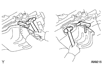
Remove the 16 bolts and 2 nuts.
Remove the oil pan by prying between the oil pan and cylinder block with a screwdriver.
- HINT:
- Tape the screwdriver tip before use.
- NOTICE:
- Be careful not to damage the contact surfaces of the cylinder block and oil pan.
 |
Remove the O-ring.
| 23. REMOVE CRANKSHAFT POSITION SENSOR |
Disconnect the sensor connector.
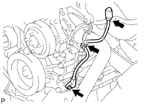 |
Disconnect the connector from the connector bracket.
Detach the harness clamp.
Remove the bolt and sensor.
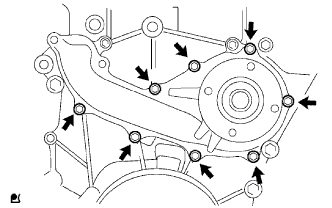
| 24. REMOVE TIMING CHAIN COVER (OIL PUMP ASSEMBLY) |
Remove the 19 bolts and 2 nuts shown in the illustration.
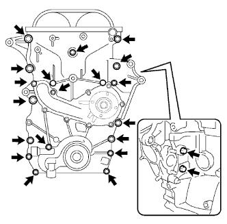 |
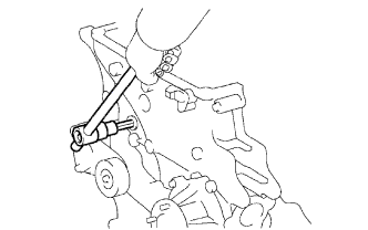
Remove the timing chain cover by prying between the timing chain cover and cylinder head or cylinder block with a screwdriver.
- HINT:
- Tape the screwdriver tip before use.
- NOTICE:
- Be careful not to damage the contact surfaces of the cylinder head, cylinder block and timing chain cover.
 |
Remove the 3 O-rings.
Using a 10 mm socket hexagon wrench, remove the timing gear case plug.
 |
| 25. REMOVE WATER PUMP |
Remove the 8 bolts, water pump and gasket.
 |
| 26. REMOVE TIMING CHAIN COVER OIL SEAL |
Place the timing chain cover on wooden blocks.
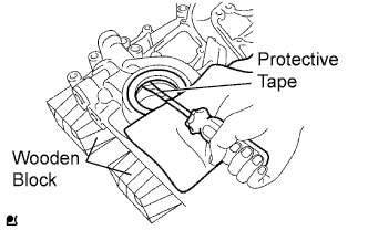 |
Using a screwdriver with its tip taped, pry out the oil seal.
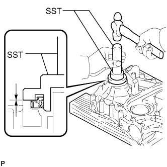
Using SST and a hammer, tap in a new oil seal until its surface is flush with the timing chain cover edge.
- SST
- 09223-75010
09950-70010 (09951-07150)
- NOTICE:
- Keep the lip free from foreign matter.
- Do not tap the oil seal at an angle.
- HINT:
- When installing the crankshaft pulley, check the shape of the pulley. The correct pulley has a groove (Click here).
 |
Apply a light coat of MP grease to a new oil seal lip.