DTC P0335 Crankshaft Position Sensor "A" Circuit |
DTC P0339 Crankshaft Position Sensor "A" Circuit Intermittent |

for Preparation Click here
DESCRIPTION
The crankshaft position sensor system consists of a sensor plate and a pickup coil.The sensor plate has 34 teeth and is installed on the crankshaft. The pickup coil is made of wound copper wire, an iron core and magnet. The sensor plate rotates and, as each tooth passes by the pickup coil, a pulse signal is created. The pickup coil generates 34 signals per crankshaft revolution. Based on these signals, the ECM calculates the crankshaft position and engine speed. Using these calculations, the fuel injection time and ignition timing are controlled.
| DTC No. | DTC Detection Condition | Trouble Area |
| P0335 | One of the following conditions is met (1 trip detection logic):
|
|
| P0339 | All of the following conditions are met (1 trip detection logic): (a) The engine speed is 1000 rpm or more. (b) No crankshaft position sensor signal for 0.05 seconds or more. (c) 3 seconds or more have elapsed since the starter signal switched from ON to OFF. |
|
Reference: Inspection using an oscilloscope.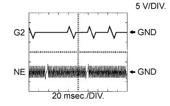
- HINT:
- G2 stands for the camshaft position sensor signal and NE stands for the crankshaft position sensor signal.
- Grounding failure of the shielded wire may cause noise in the waveforms.
Tester Connection Tool Setting Condition Specified Condition E11-27 (NE+) - E11-34 (NE-) 5 V/DIV, 20 msec./DIV Idling The correct waveform is as shown E11-26 (G2) - E11-34 (NE-) 5 V/DIV, 20 msec./DIV Idling The correct waveform is as shown
MONITOR DESCRIPTION
If there is no signal from the crankshaft position sensor despite the crankshaft revolving, the ECM interprets this as a malfunction of the sensor.If the malfunction is not repaired successfully, a DTC is stored 10 seconds after the engine is next started.
MONITOR STRATEGY
| Required Sensors/Components (Main) | Crankshaft position sensor |
| Required Sensors/Components (Related) | Camshaft position sensor |
| Frequency of Operation | Continuous |
COMPONENT OPERATING RANGE
| Crankshaft position sensor |
|
CONFIRMATION DRIVING PATTERN
- Start the engine and run it at idle for 20 seconds or more.
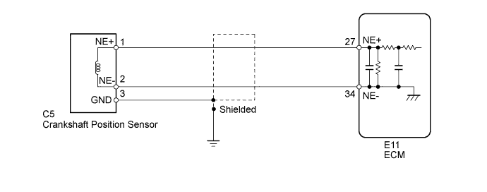
WIRING DIAGRAM
INSPECTION PROCEDURE
- HINT:
- After performing the inspection procedure for the crankshaft position sensor, if DTC P0335 is output again, check the following items related to the camshaft position sensor.
- Installation condition of the camshaft position sensor
- Installation condition of the camshaft
- Connection of the camshaft position sensor connector
- HINT:
- If no problem is found by this diagnostic troubleshooting procedure, check for problems by referring to the engine mechanical section.
- The engine speed can be checked by using the intelligent tester. To perform the check, follow the procedures below:
- Connect the intelligent tester to the DLC3.
- Start the engine.
- Turn the intelligent tester on.
- Enter the following menus: Powertrain / Engine and ECT / Data List / All Data / Engine Speed.
- The engine speed may be indicated as zero despite the engine running normally. This is caused by a lack of NE signals from the crankshaft position sensor. Alternatively, the engine speed may be indicated as lower than the actual engine speed if the crankshaft position sensor output voltage is insufficient.
- Read freeze frame data using the intelligent tester. Freeze frame data records the engine conditions when malfunctions are detected. When troubleshooting, freeze frame data can help determine if the vehicle was moving or stationary, if the engine was warmed up or not, if the air-fuel ratio was lean or rich, and other data from the time the malfunction occurred.
| 1.READ VALUE USING INTELLIGENT TESTER (ENGINE SPEED) |
Connect the intelligent tester to the DLC3.
Turn the ignition switch to ON.
Turn the intelligent tester on.
Enter the following menus: Powertrain / Engine and ECT / Data List / All Data / Engine Speed.
Start the engine.
Read the values displayed on the intelligent tester while the engine is running.
- Standard:
- Correct values are displayed.
- HINT:
- To check the engine speed change, display the graph on the intelligent tester.
- If the engine does not start, check the engine speed while cranking.
- If the engine speed indicated on the intelligent tester remains at zero (0), there may be an open or short in the crankshaft position sensor circuit.
|
| ||||
| OK | ||
| ||
| 2.INSPECT CRANKSHAFT POSITION SENSOR (RESISTANCE) |
Inspect the crankshaft position sensor (Click here).
|
| ||||
| OK | |
| 3.CHECK HARNESS AND CONNECTOR (CRANKSHAFT POSITION SENSOR - ECM) |
Disconnect the crankshaft position sensor connector.
Disconnect the ECM connector.
Measure the resistance according to the value(s) in the table below.
- Standard Resistance:
Tester Connection Condition Specified Condition C5-1 (NE+) - E11-27 (NE+) Always Below 1 Ω C5-2 (NE-) - E11-34 (NE-) Always Below 1 Ω C5-1 (NE+) or E11-27 (NE+) - Body ground Always 10 kΩ or higher C5-2 (NE-) or E11-34 (NE-) - Body ground Always 10 kΩ or higher
|
| ||||
| OK | |
| 4.CHECK SENSOR INSTALLATION (CRANKSHAFT POSITION SENSOR) |
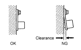 |
Check the crankshaft position sensor installation.
- OK:
- Sensor is installed correctly.
|
| ||||
| OK | |
| 5.INSPECT NO. 2 CRANKSHAFT TIMING SPROCKET (TEETH OF SENSOR PLATE) |
Check the teeth of the sensor plate.
- OK:
- Sensor plate does not have any cracks or deformation.
|
| ||||
| OK | |
| 6.REPLACE CRANKSHAFT POSITION SENSOR |
Replace the crankshaft position sensor (Click here).
| NEXT | |
| 7.CHECK WHETHER DTC OUTPUT RECURS (DTC P0335 AND/OR P0339) |
Connect the intelligent tester to the DLC3.
Turn the ignition switch to ON.
Turn the intelligent tester on.
Clear the DTCs (Click here).
Start the engine.
Enter the following menus: Powertrain / Engine and ECT / DTC.
Read the DTCs.
Result Result Proceed to No DTC is output A P0335 or P0339 is output B - HINT:
- If the engine does not start, replace the ECM.
|
| ||||
| A | ||
| ||