DTC P2121 Throttle / Pedal Position Sensor / Switch "D" Circuit Range / Performance |

for Preparation Click here
DESCRIPTION
- HINT:
- These DTCs are related to the accelerator pedal position sensor. The troubleshooting procedures for the accelerator pedal position sensor are in the flowchart below.
- Refer to DTC P2120 (Click here).
| DTC No. | DTC Detection Condition | Trouble Area |
| P2121 | Conditions (a) and (b) continue for 0.5 seconds: (a) Difference between VPA1 and VPA2 exceeds the threshold (b) IDL is OFF |
|
WIRING DIAGRAM
Refer to DTC P2120 (Click here).INSPECTION PROCEDURE
- HINT:
- Read freeze frame data using the intelligent tester. Freeze frame data records the engine conditions when a malfunction is detected. When troubleshooting, freeze frame data can help determine if the vehicle was running or stopped, if the engine was warmed up or not, if the air fuel ratio was lean or rich, and other data from the time the malfunction occurred.
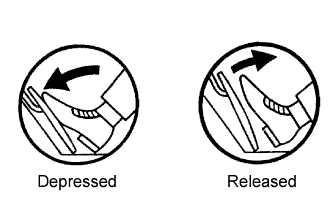
| 1.READ VALUE USING INTELLIGENT TESTER (ACCELERATOR POSITION NO. 1, ACCELERATOR POSITION NO. 2) |
 |
Connect the intelligent tester to the DLC3.
Turn the ignition switch ON and turn the tester ON.
Enter the following menus: Powertrain / Engine and ECT / Data List / Accelerator Position No. 1 and Accelerator Position No. 2.
Read the value.
- Standard voltage:
Accelerator Pedal No. 1 Accelerator Position No. 2 Accelerator Position Released 0.5 to 1.1 V 1.2 to 2.0 V Depressed 2.6 to 4.5 V 3.4 to 5.0 V
|
| ||||
| NG | |
| 2.CHECK WIRE HARNESS (ACCELERATOR PEDAL POSITION SENSOR - ECM) |
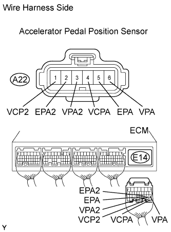 |
Disconnect the A22 accelerator pedal position sensor connector.
Disconnect the E14 ECM connector.
Measure the resistance of the wire harness side connectors.
- Standard resistance:
Tester Connection Specified Condition A22-6 (VPA) - E14-18 (VPA) Below 1 Ω A22-5 (EPA) - E14-20 (EPA) Below 1 Ω A22-4 (VCPA) - E14-26 (VCPA) Below 1 Ω A22-3 (VPA2) - E14-19 (VPA2) Below 1 Ω A22-2 (EPA2) - E14-21 (EPA2) Below 1 Ω A22-1 (VCP2) - E14-27 (VCP2) Below 1 Ω A22-6 (VPA) or E14-18 (VPA) - Body ground 10 kΩ or higher A22-5 (EPA) or E14-20 (EPA) - Body ground 10 kΩ or higher A22-4 (VCPA) or E14-26 (VCPA) - Body ground 10 kΩ or higher A22-3 (VPA2) or E14-19 (VPA2) - Body ground 10 kΩ or higher A22-2 (EPA2) or E14-21 (EPA2) - Body ground 10 kΩ or higher A22-1 (VCP2) or E14-27 (VCP2) - Body ground 10 kΩ or higher
|
| ||||
| OK | |
| 3.REPLACE ACCELERATOR PEDAL ROD ASSEMBLY |
| NEXT | |
| 4.CHECK WHETHER DTC OUTPUT RECURS (ACCELERATOR PEDAL POSITION SENSOR DTCS) |
Connect the intelligent tester to the DLC3.
Turn the ignition switch ON and turn the tester ON.
Clear DTCs (Click here).
Start the engine.
Allow the engine to idle for 15 seconds.
Enter the following menus: Powertrain / Engine and ECT / DTC.
Read DTCs.
- Result:
Display (DTC Output) Proceed to P2121 A No output B
|
| ||||
| A | ||
| ||