ENGINE ASSEMBLY > REMOVAL |

for Preparation Click here
| 1. DISCHARGE FUEL SYSTEM PRESSURE |
- HINT:
| 2. ALIGN FRONT WHEELS FACING STRAIGHT AHEAD |
| 3. REMOVE FRONT WHEEL |
| 4. REMOVE ENGINE UNDER COVER LH |
| 5. REMOVE ENGINE UNDER COVER RH |
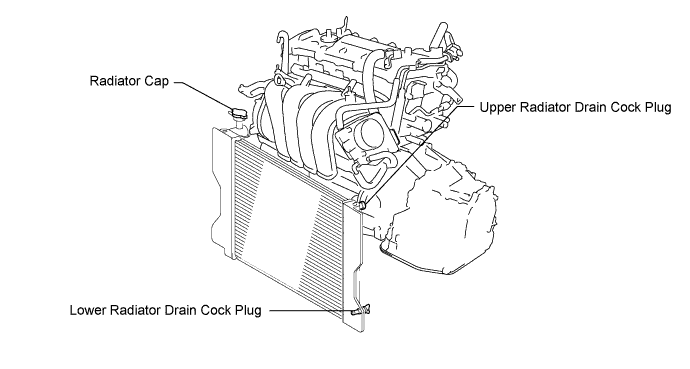
| 6. DRAIN ENGINE COOLANT |
Loosen the lower radiator drain cock plug.
- CAUTION:
- Do not loosen the lower radiator drain cock plug while the engine and radiator are still hot.
- Pressurized, hot engine coolant and steam may be released and cause serious burns.
- HINT:
- Collect the coolant in a container and dispose of it according to the regulations in your area.
Remove the radiator cap.
| 7. DRAIN ENGINE OIL |
Remove the oil filler cap.
Remove the oil drain plug and drain the oil into a container.
Clean and install the oil drain plug with a new gasket.
- Torque:
- 37 N*m{ 377 kgf*cm , 27 ft.*lbf }
| 8. DRAIN MANUAL TRANSAXLE OIL (for Manual Transaxle) |
- HINT:
- Click here for C59.
| 9. DRAIN AUTOMATIC TRANSAXLE FLUID (for Automatic Transaxle) |
- HINT:
- Click here for U341E.
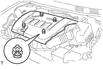
| 10. REMOVE NO. 2 CYLINDER HEAD COVER |
Hold the rear of the cover and raise it to disengage the 2 clips on the rear of the cover. Continue to raise the cover to disengage the 2 clips on the front of the cover to remove the cover.
- NOTICE:
- Attempting to disengage both front and rear clips at the same time may cause the cover to break.
 |
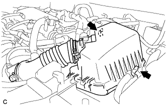
| 11. REMOVE AIR CLEANER CAP SUB-ASSEMBLY |
Disconnect the mass air flow meter connector and the 2 wire harness clamps.
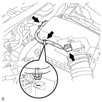 |
Disconnect the ventilation hose and loosen the hose clamp.
 |
Release the 2 clamps and remove the air cleaner cap sub-assembly with hose.
 |
| 12. REMOVE AIR CLEANER CASE |
Separate the air cleaner filter element from the air cleaner.
Disconnect the engine wire harness clamp from air cleaner case.
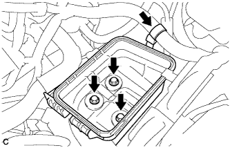 |
Remove the 3 bolts and the air cleaner case.
| 13. REMOVE BATTERY |
Disconnect the battery cables.
Remove the bolt and loosen the nut.
Remove the battery.
| 14. REMOVE BATTERY CARRIER |
Separate the 2 wire harness clamps from the battery carrier.
 |
Remove the 2 bolts.
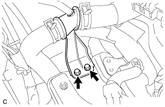 |
Separate the radiator pipe from the battery carrier.
Remove the 4 bolts and battery carrier.
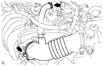
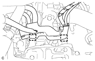
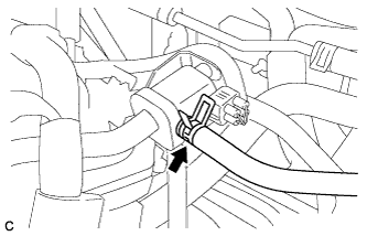
| 15. DISCONNECT NO. 1 RADIATOR HOSE |
Disengage the clamp*1.
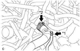 |
Disconnect the No. 1 radiator hose from the cylinder head with the clamp*2.
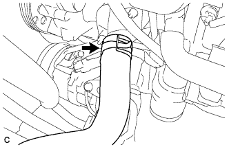
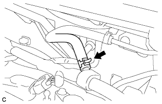
| 16. DISCONNECT NO. 2 RADIATOR HOSE |
Disconnect the No. 2 radiator hose from the water inlet hose.
 |
| 17. DISCONNECT TRANSMISSION CONTROL CABLE ASSEMBLY (for Manual Transaxle) |
Remove the 2 clips and disconnect the 2 cables from the transaxle.
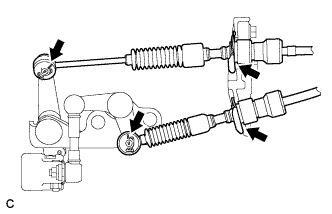 |
Remove the 2 clips and disconnect the 2 cables from the control cable bracket.
| 18. DISCONNECT TRANSMISSION CONTROL CABLE ASSEMBLY (for Automatic Transaxle) |
Disconnect the control cable from the control cable support.
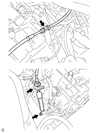 |
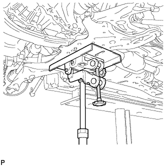
Remove the nut and disconnect the control cable from the control shaft lever.
Remove the clip and disconnect the control cable from the control cable bracket.
Remove the bolt and disconnect the clamp of the control cable.
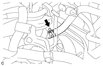
| 19. DISCONNECT FUEL VAPOR FEED HOSE ASSEMBLY |
Disconnect the fuel vapor feed hose.
 |
| 20. DISCONNECT UNION TO CONNECTOR TUBE HOSE |
Disconnect the union to connector tube hose.
 |
| 21. DISCONNECT OIL COOLER HOSE (for Automatic Transaxle) |
Disconnect the 2 oil cooler hoses from the oil cooler tube.
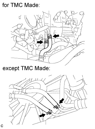 |
| 22. DISCONNECT OUTLET HEATER WATER HOSE |
Disconnect the outlet heater water hose from the engine.
 |
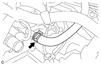
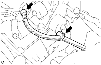
| 23. DISCONNECT INLET HEATER WATER HOSE |
Disconnect the inlet heater water hose from the engine.
 |
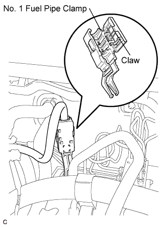
| 24. DISCONNECT FUEL TUBE SUB-ASSEMBLY |
Release the claw and remove the No. 1 fuel pipe clamp.
 |
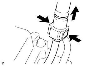
Pinch the retainer as illustrated, then pull the fuel tube connector out of the pipe.
- NOTICE:
- Remove any dirt and foreign matter from the fuel tube connector before performing this work.
- Do not allow any scratches or foreign matter on the parts when disconnecting, as the fuel tube connector has the O-rings that seal the pipe.
- Perform this work by hand. Do not use any tools.
- Do not forcibly bend, kink or twist the nylon tube.
- Protect the disconnected parts by covering them with vinyl bags after disconnecting the fuel tube.
- If the fuel tube connector and pipe are stuck, push and pull to release them.
 |
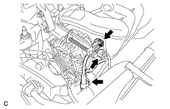
| 25. REMOVE V-RIBBED BELT |
Loosen bolts A and B.
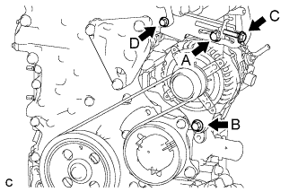 |
Loosen bolt C, then remove the V-ribbed belt.
- NOTICE:
- Do not loosen bolt D.
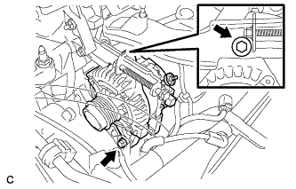
| 26. REMOVE GENERATOR ASSEMBLY |
Remove the terminal cap.
 |
Remove the nut and disconnect the wire harness from terminal B.
Disconnect the connector and harness clamp.
Remove the 2 bolts and generator assembly.
 |
Remove the bolt and wire harness clamp bracket.
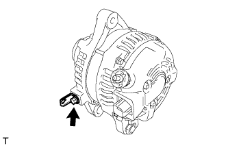 |
| 27. REMOVE FAN BELT ADJUSTING BAR |
Remove the bolt and fan belt adjusting bar.
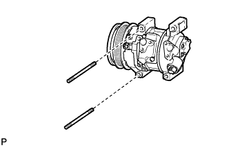
| 28. SEPARATE COMPRESSOR ASSEMBLY WITH PULLEY (w/ Air Conditioning System) |
Disconnect the connector.
Remove the 2 bolts and 2 nuts.
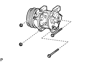 |
Using a "TORX" socket wrench (E8), remove the 2 stud bolts and compressor assembly with pulley.
- HINT:
- Secure the compressor and hoses off to the side instead of discharging the A/C system.
 |
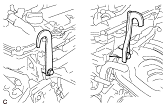
| 29. SEPARATE CLUTCH RELEASE CYLINDER ASSEMBLY (for Manual Transaxle) |
Remove the 4 bolts and clutch tube bracket, and separate the clutch release cylinder assembly.
 |
| 30. DISCONNECT WIRE HARNESS |
Pull up the lever to disconnect the ECM connector and release the clamp.
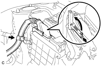 |
Remove the 2 nuts.
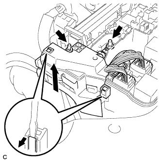 |
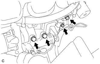
Remove the 3 connectors and 2 clamps from the engine room junction block and disconnect the wire harness.
Remove the bolt and clamp (for Manual Transaxle).
 |
Remove the bolt and clamp (for Automatic Transaxle).
 |
Disconnect all the wire harnesses and connectors.
Make sure that no wire harness is connected between the body and engine.
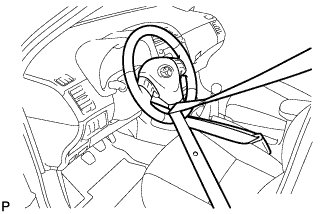
| 31. SECURE STEERING WHEEL |
Secure the steering wheel with the seat belt in order to prevent rotation.
- HINT:
- This operation is useful to prevent damage to the spiral cable.
 |
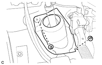
| 32. REMOVE COLUMN HOLE COVER SILENCER SHEET |
Turn back the floor carpet, and remove the 2 clips and column hole cover silencer sheet.
 |
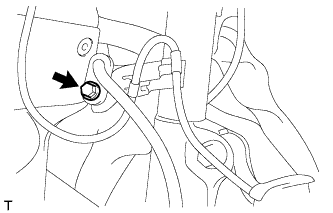
| 33. SEPARATE NO. 2 STEERING INTERMEDIATE SHAFT ASSEMBLY |
Put matchmarks on the No. 2 steering intermediate shaft assembly and the steering intermediate shaft.
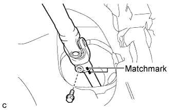 |
Remove the bolt and separate the No. 2 steering intermediate shaft assembly from the steering intermediate shaft.
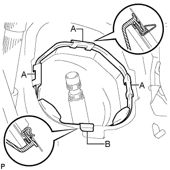
| 34. DISCONNECT NO. 1 STEERING COLUMN HOLE COVER SUB-ASSEMBLY |
Remove clips A and the No. 1 steering column hole cover sub-assembly and disengage clip B from the body.
- NOTICE:
- Do not damage clips A and B.
 |
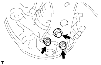
| 35. REMOVE FRONT EXHAUST PIPE ASSEMBLY |
Disconnect the heated oxygen sensor connector.
Remove the 4 bolts and 4 compression springs.
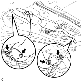 |
Remove the front exhaust pipe assembly from the 2 exhaust pipe supports.
Remove the 2 gaskets.
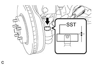
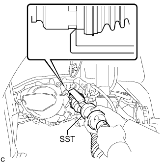
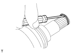
| 36. REMOVE FRONT AXLE SHAFT NUT LH |
Using SST and a hammer, release the staked part of the front axle shaft nut LH.
- SST
- 09930-00010
- NOTICE:
- Insert SST into the groove with the flat surface facing up.
- Do not damage the tip of SST using grinders.
- Completely unstake the staked part before removing the front axle shaft nut.
- Do not damage the threads of the drive shaft.
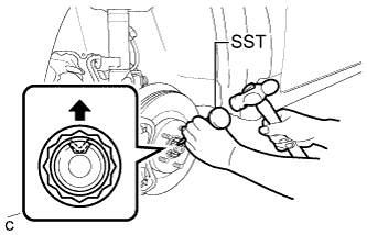 |
Using a socket wrench (30 mm), remove the front axle shaft nut LH.
| 37. REMOVE FRONT AXLE SHAFT NUT RH |
- HINT:
- Perform the same procedure for the LH side.
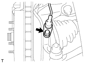
| 38. DISCONNECT FRONT SPEED SENSOR LH |
Remove the bolt and separate the front speed sensor and flexible hose from the front shock absorber bracket.
 |
Remove the bolt and separate the front speed sensor from the steering knuckle.
- NOTICE:
- Keep the front speed sensor tip and installation surfaces free of foreign matter.
- Remove the front speed sensor without turning it from its original installation angle.
 |
| 39. DISCONNECT FRONT SPEED SENSOR RH |
- HINT:
- Perform the same procedure for the LH side.
| 40. SEPARATE TIE ROD END SUB-ASSEMBLY LH |
Remove the cotter pin and the nut.
Install SST to the tie rod end.
- SST
- 09960-20010
(09961-02060)
- NOTICE:
- Make sure that the upper ends of the tie rod end and SST are aligned.
 |
Using SST, separate the tie rod end from the steering knuckle.
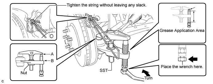
- SST
- 09960-20010
(09961-02010)
- CAUTION:
- Apply grease to the threads of the bolt and the tip of SST.
- NOTICE:
- Be sure to tighten the string firmly to secure SST to the steering knuckle to prevent SST from falling off.
- Install SST with the center nut so that A and B are parallel. Otherwise, the dust cover may be damaged.
- Be sure to place the wrench on the part indicated in the illustration.
- Do not damage the front disc brake dust cover.
- Do not damage the ball joint dust cover.
- Do not damage the steering knuckle.
| 41. SEPARATE TIE ROD END SUB-ASSEMBLY RH |
- HINT:
- Perform the same procedure for the LH side.
| 42. SEPARATE FRONT STABILIZER LINK ASSEMBLY LH |
Remove the nut and separate the stabilizer link assembly from the front shock absorber with coil spring.
- NOTICE:
- If the ball joint turns together with the nut, use a hexagon wrench (6 mm) to hold the stud bolt.
 |
| 43. SEPARATE FRONT STABILIZER LINK ASSEMBLY RH |
- HINT:
- Perform the same procedure for the LH side.
| 44. SEPARATE FRONT LOWER SUSPENSION ARM LH |
Remove the bolt and 2 nuts, and separate the front lower suspension arm from the lower ball joint.
 |
| 45. SEPARATE FRONT LOWER SUSPENSION ARM RH |
- HINT:
- Perform the same procedure for the LH side.
| 46. SEPARATE STEERING KNUCKLE WITH AXLE HUB LH |
Put matchmarks on the drive shaft and axle hub.
- NOTICE:
- Do not punch the marks.
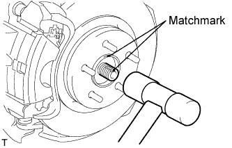 |
Using a plastic-faced hammer, disconnect the front axle assembly LH.
- NOTICE:
- Be careful not to damage the boot and speed sensor rotor.
- Do not excessively push out the drive shaft from the axle assembly.
| 47. SEPARATE STEERING KNUCKLE WITH AXLE HUB RH |
- HINT:
- Perform the same procedure for the LH side.
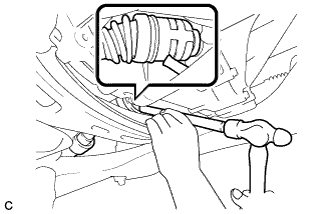
| 48. REMOVE FRONT DRIVE SHAFT ASSEMBLY LH |
Using SST, remove the front drive shaft assembly LH.
- SST
- 09520-01010
09520-24010 (09520-32040)
- NOTICE:
- Do not damage the oil seal.
- Do not damage the inboard joint boot.
- Do not drop the drive shaft.
 |
| 49. REMOVE FRONT DRIVE SHAFT ASSEMBLY RH |
Using a brass bar and hammer, remove the front drive shaft assembly RH.
- NOTICE:
- Do not damage the oil seal.
- Do not damage the inboard joint boot.
- Do not drop the drive shaft.
 |
| 50. REMOVE FRONT DRIVE SHAFT HOLE SNAP RING LH |
Using a screwdriver, remove the front drive shaft hole snap ring LH from the front drive inboard joint assembly LH.
 |
| 51. REMOVE FRONT DRIVE SHAFT HOLE SNAP RING RH |
- HINT:
- Perform the same procedure as for the LH side.
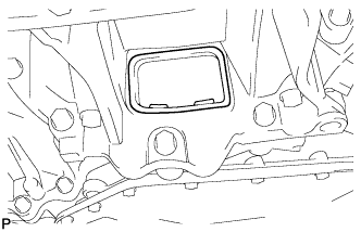
| 52. REMOVE FLYWHEEL HOUSING UNDER COVER (for Automatic Transaxle) |
Remove the flywheel housing under cover.
 |
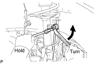
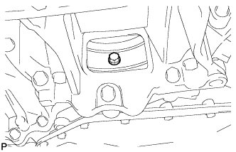
| 53. REMOVE DRIVE PLATE AND TORQUE CONVERTER ASSEMBLY SETTING BOLT (for Automatic Transaxle) |
Remove the 6 torque converter assembly setting bolts while holding the crankshaft pulley bolt with a wrench.
- NOTICE:
- One of the 6 bolts has a different color than the other ones.
 |
| 54. REMOVE FRONT SUSPENSION CROSSMEMBER SUB-ASSEMBLY |
Remove the 3 bolts and 3 nuts.
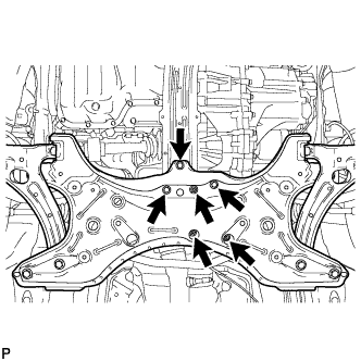 |
Using a transmission jack or equivalent, support the front suspension crossmember sub-assembly.
 |
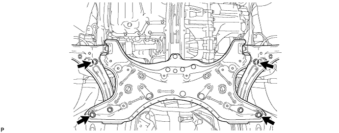
Remove the 4 bolts and front suspension crossmember sub-assembly.
| 55. REMOVE CENTER ENGINE MOUNTING MEMBER SUB-ASSEMBLY |
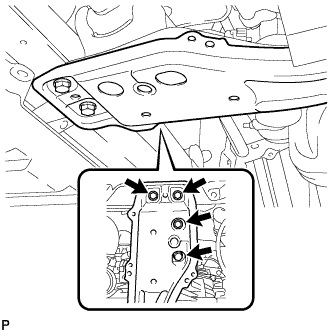
Remove the 4 bolts and center engine mounting member sub-assembly.
 |
| 56. REMOVE ENGINE ASSEMBLY WITH TRANSAXLE |
Set the engine lifter.
- NOTICE:
- Place the engine on wooden blocks or equivalent so that the engine is level.
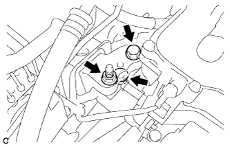
Remove the bolt and 2 nuts, and separate the engine mounting insulator RH.
 |
Remove the through bolt and nut, and separate the engine mounting insulator LH.
 |
Carefully remove the engine with transaxle from the vehicle.
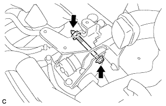
| 57. REMOVE FRONT ENGINE MOUNTING INSULATOR |
Remove the bolt, nut and front engine mounting insulator.
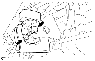 |
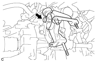
| 58. REMOVE REAR ENGINE MOUNTING INSULATOR |
Remove the through bolt and rear engine mounting insulator.
 |
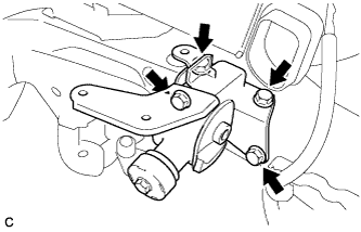
| 59. REMOVE ENGINE MOUNTING INSULATOR LH |
Remove the 4 bolts and engine mounting insulator LH.
- HINT:
- Perform this procedure only when replacement of the engine mounting insulator is necessary.
 |
| 60. REMOVE ENGINE MOUNTING INSULATOR RH |
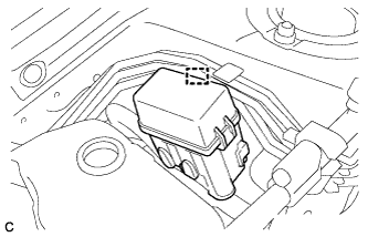
Disconnect the clamp, and release the relay block assembly.
 |
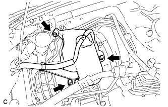
Remove the 3 bolts and radiator reserve tank.
 |
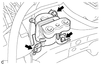
Remove the 3 bolts and engine mounting insulator RH.
- HINT:
- Perform this procedure only when replacement of the engine mounting insulator is necessary.
 |
| 61. INSTALL ENGINE HANGER |
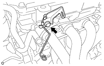
Remove the bolt and wire harness bracket.
 |
Install the 2 engine hangers with the 2 bolts.
- Torque:
- 43 N*m{ 439 kgf*cm , 32 ft.*lbf }
Part Name Part No. No. 1 engine hanger 12281-37021 No. 2 engine hanger 12282-37011 Bolt 91552-81050
 |
| 62. REMOVE FLYWHEEL HOUSING SIDE COVER |
| 63. REMOVE STARTER ASSEMBLY |
Remove the terminal cap.
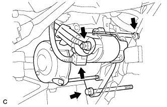 |
Remove the nut and disconnect terminal 30.
Disconnect the connector.
Remove the 2 bolts and starter assembly.
| 64. REMOVE MANUAL TRANSAXLE ASSEMBLY (for Manual Transaxle) |
- HINT:
- Click here for C59.
| 65. REMOVE AUTOMATIC TRANSAXLE ASSEMBLY (for Automatic Transaxle) |
- HINT:
- Click here for U341E.
| 66. REMOVE CLUTCH COVER ASSEMBLY (for Manual Transaxle) |
Put matchmarks on the clutch cover assembly and the flywheel sub-assembly.
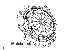 |
Loosen each set bolt one turn at a time until the spring tension is released.
Remove the set bolts and pull off the clutch cover.
- NOTICE:
- Do not drop the clutch disc.
| 67. REMOVE CLUTCH DISC ASSEMBLY (for Manual Transaxle) |
- NOTICE:
- Keep the parts clutch disc lining, the pressure plate, and the surface of the flywheel sub-assembly free of oil and foreign matter.
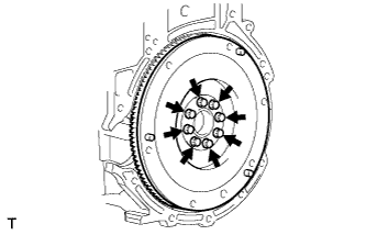
| 68. REMOVE FLYWHEEL SUB-ASSEMBLY (for Manual Transaxle) |
Using SST, hold the crankshaft.
- SST
- 09213-58014
(91551-80840)
09330-00021
- NOTICE:
- Check the SST installation positions when installing them to prevent the SST fixing bolts from coming into contact with the timing chain cover sub-assembly.
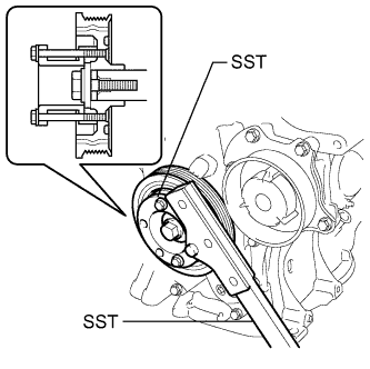 |
Remove the 8 bolts and flywheel.
 |
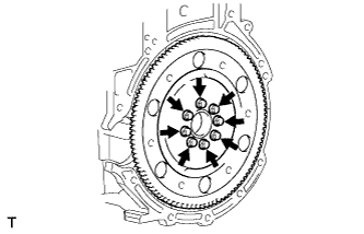
| 69. REMOVE DRIVE PLATE AND RING GEAR SUB-ASSEMBLY (for Automatic Transaxle) |
Using SST, hold the crankshaft.
- SST
- 09213-58014
(91551-80840)
09330-00021
- NOTICE:
- Check the SST installation positions when installing them to prevent the SST fixing bolts from coming into contact with the timing chain cover sub-assembly.
|
Remove the 8 bolts, rear spacer, drive plate and front spacer.
 |
| 70. REMOVE ENGINE WIRE |