POWER STEERING SYSTEM (for 2AZ-FE) > EPS Warning Light Circuit |

for Preparation Click here
DESCRIPTION
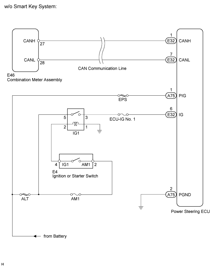
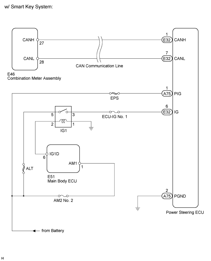
If the power steering ECU detects a malfunction, the P/S warning light comes on. At this time, the power steering ECU stores a DTC in its memory.WIRING DIAGRAM
INSPECTION PROCEDURE
- NOTICE:
- If the steering column assembly or power steering ECU has been replaced, perform the rotation angle sensor initialization and torque sensor zero point calibration (Click here ).
| 1.CHECK FOR DTC (CAN COMMUNICATION SYSTEM) |
Check for DTCs.
- OK:
- DTC is not output.
|
| ||||
| OK | |
| 2.CHECK HARNESS AND CONNECTOR (POWER STEERING ECU - BODY GROUND) |
Disconnect the connectors from the power steering ECU.
Measure the voltage according to the value(s) in the table below.
- Standard Voltage:
Tester Connection Switch Condition Specified Condition E32-6 (IG) - A75-2 (PGND) Ignition switch on (IG) 11 to 14 V
Measure the resistance according to the value(s) in the table below.
- Standard Resistance:
Tester Connection Switch Condition Specified Condition A75-2 (PGND) - Body ground Always Below 1 Ω
|
| ||||
| A | |
| 3.REPLACE POWER STEERING ECU |
Replace the power steering ECU (Click here).
Check the P/S warning light condition.
- OK:
- P/S warning light operates normally.
|
| ||||
| OK | ||
| ||