REAR AXLE HUB > INSTALLATION |

for Preparation Click here
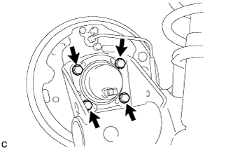
| 1. INSTALL REAR AXLE HUB AND BEARING ASSEMBLY (for Rear Drum Brake) |
Install the rear axle hub and bearing assembly with the 4 bolts.
- Torque:
- 100 N*m{ 1020 kgf*cm , 74 ft.*lbf }
 |
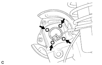
| 2. INSTALL REAR AXLE HUB AND BEARING ASSEMBLY (for Rear Disc Brake) |
Install the rear axle hub and bearing assembly with the 4 bolts.
- Torque:
- 100 N*m{ 1020 kgf*cm , 74 ft.*lbf }
 |
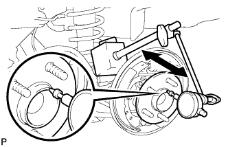
| 3. INSPECT REAR AXLE HUB BEARING LOOSENESS (for Rear Drum Brake) |
Using a dial indicator, check for looseness near the center of the axle hub.
- Maximum looseness:
- 0.05 mm (0.00196 in.)
- NOTICE:
- Ensure that the dial indicator is set perpendicular to the measurement surface.
 |
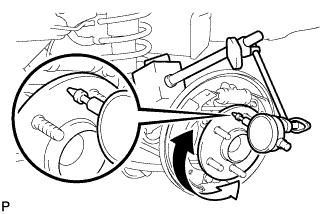
| 4. INSPECT REAR AXLE HUB RUNOUT (for Rear Drum Brake) |
Using a dial indicator, check for runout on the surface of the axle hub outside the hub bolt.
- Maximum runout:
- 0.06 mm (0.00236 in.)
- NOTICE:
- Ensure that the dial indicator is set perpendicular to the measurement surface.
 |
| 5. INSPECT REAR AXLE HUB BEARING LOOSENESS (for Rear Disc Brake) |
Using a dial indicator, check for looseness near the center of the axle hub.
- Maximum looseness:
- 0.05 mm (0.00196 in.)
- NOTICE:
- Ensure that the dial indicator is set perpendicular to the measurement surface.
 |
| 6. INSPECT REAR AXLE HUB RUNOUT (for Rear Disc Brake) |
Using a dial indicator, check for runout on the surface of the axle hub outside the hub bolt.
- Maximum runout:
- 0.06 mm (0.00236 in.)
- NOTICE:
- Ensure that the dial indicator is set perpendicular to the measurement surface.
 |
| 7. INSTALL REAR BRAKE DRUM (for Rear Drum Brake) |
Install the rear brake drum.
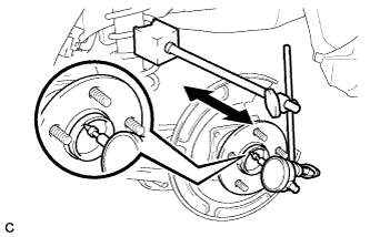
| 8. ADJUST REAR DRUM BRAKE SHOE CLEARANCE (for Rear Drum Brake) |
Temporarily install the 2 wheel nuts.
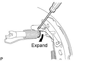 |
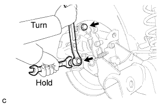
Remove the shoe adjusting hole plug, and turn the adjuster to expand the shoe until the drum locks.
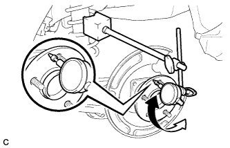
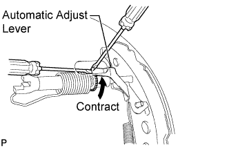
Hold the automatic adjust lever away from the adjuster, and contract the brake shoe by turning the adjust bolt using another screwdriver until the drum can rotate smoothly.
- Standard:
- 11 notches
 |
Install the hole plug.
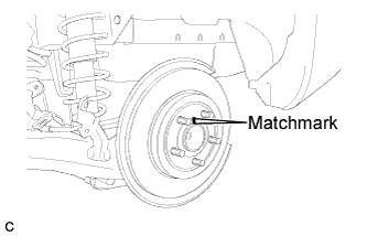
| 9. INSTALL REAR DISC (for Rear Disc Brake) |
Align the matchmarks of the disc and axle hub and install the disc.
- NOTICE:
- When replacing the disc with a new one, select the installation position where the rear disc has minimal runout.
 |
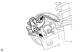
| 10. INSTALL REAR DISC BRAKE CALIPER ASSEMBLY (for Rear Disc Brake) |
Install the rear disc brake caliper assembly with the 2 bolts.
- Torque:
- 63 N*m{ 642 kgf*cm , 46 ft.*lbf }
 |
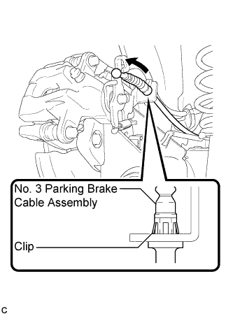
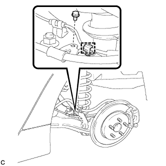
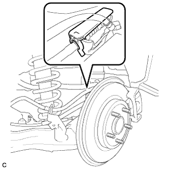
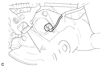
| 11. CONNECT NO. 3 PARKING BRAKE CABLE ASSEMBLY (for Rear Disc Brake) |
Install the No. 3 parking brake cable assembly to the rear disc brake cylinder assembly LH.
- HINT:
- Be sure to engage the No. 3 parking brake cable assembly clip onto the rear disc brake cylinder assembly LH as shown in the illustration.
 |
Connect the No. 3 parking brake cable assembly to the rear disc brake cylinder assembly LH.
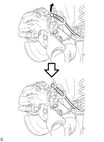 |
Install the bolt.
- Torque:
- 6.0 N*m{ 61 kgf*cm , 53 in.*lbf }
 |
Engage the clamp to the No. 3 parking brake cable assembly.
| 12. ADJUST PARKING BRAKE LEVER TRAVEL (for Rear Disc Brake) |
Remove the upper console box assembly (Click here).
Completely release the parking brake lever.
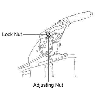
Loosen the lock nut and the adjusting nut to completely release the parking brake cable.
 |
Fully depress the brake lever 3 to 5 times with the engine stopped.
Turn the adjusting nut until the parking brake lever travel is corrected to within the specified range.
- Parking brake lever travel:
- 6 to 9 notches at 200 N (20 kgf, 45.0 lbf)
Using a wrench or an equivalent tool, hold the adjusting nut and tighten the lock nut.
- Torque:
- 6.0 N*m{ 61 kgf*cm , 53 in.*lbf }
Operate the parking brake lever 3 to 4 times, and check the parking brake lever travel.
Check whether the parking brake drags or not.
Install the upper console box assembly (Click here).
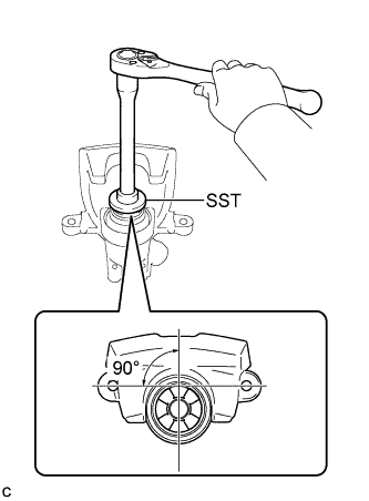
| 13. INSPECT REAR DISC BRAKE CYLINDER OPERATION LEVER AND STOPPER CLEARANCE (for Rear Disc Brake) |
To compensate for pad lining thickness, use SST to adjust the protrusion of the rear disc brake piston by turning it.
- SST
- 09719-12010
(09719-01030)
- NOTICE:
- Place the disc between the 2 brake pads and determine the piston return value.
- Turn the rear disc brake piston to the position where the protrusion on the rear disc brake pad lines up properly with the piston groove.
 |
Hold the rear disc brake cylinder slide pin, and install the rear disc brake cylinder assembly to the rear disc brake cylinder mounting with the 2 bolts.
- Torque:
- 35 N*m{ 357 kgf*cm , 26 ft.*lbf }
 |
| 14. INSTALL PARKING BRAKE LEVER PROTECTOR (for Rear Disc Brake) |
Install the parking brake lever protector to the No. 3 parking brake cable assembly.
 |
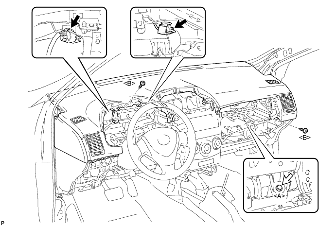
| 15. INSTALL UPPER CONSOLE PANEL SUB-ASSEMBLY (for Rear Disc Brake) |
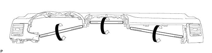
When using a new upper instrument panel sub-assembly:
Immediately before installing the upper instrument panel sub-assembly, twist and cut off the portions shown in the illustration (joints for moulding).
Install the upper instrument panel sub-assembly and engage the 5 claws.
- NOTICE:
- When installing the upper instrument panel sub-assembly, be careful not to damage it or the steering wheel assembly.
- Do not allow the wire harness to get caught in the claws.
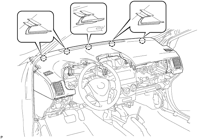
Engage the 5 clips and 4 guides.
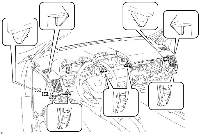
Install the 2 screws <B>.
Install the passenger airbag bolt <A>.
- Torque:
- 20 N*m{ 204 kgf*cm , 15 ft.*lbf }
Connect each connector.
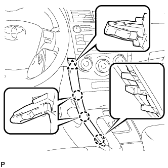
| 16. INSTALL CENTER INSTRUMENT CLUSTER FINISH PANEL ASSEMBLY (for Rear Disc Brake) |
- HINT:
- for Manual Transaxle (Click here)
- for Automatic Transaxle (Click here)
| 17. INSTALL SHIFT LEVER KNOB SUB-ASSEMBLY (for Rear Disc Brake) |
- HINT:
- for Manual Transaxle (Click here)
- for Automatic Transaxle (Click here)
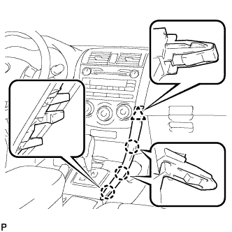
| 18. INSTALL LOWER INSTRUMENT PANEL FINISH PANEL LH (for Rear Disc Brake) |
Engage the 3 claws and clip, and then install the lower instrument panel finish panel LH.
 |
| 19. INSTALL LOWER INSTRUMENT PANEL FINISH PANEL RH (for Rear Disc Brake) |
Engage the 3 claws and clip, and then install the lower instrument panel finish panel RH.
 |
| 20. CONNECT REAR SPEED SENSOR WIRE (for Rear Drum Brake) |
Connect the rear speed sensor wire connector to the rear speed sensor.
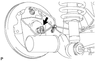 |
| 21. CONNECT REAR SPEED SENSOR WIRE (for Rear Disc Brake) |
Connect the rear speed sensor wire connector to the rear speed sensor.
 |
| 22. CONNECT CABLE TO NEGATIVE BATTERY TERMINAL |
| 23. INSTALL REAR WHEEL |
- Torque:
- 103 N*m{ 1050 kgf*cm , 76 ft.*lbf }
| 24. INSPECT REAR WHEEL ALIGNMENT |
- HINT:
| 25. CHECK FOR SPEED SENSOR SIGNAL (w/ ABS) |
- HINT:
| 26. CHECK FOR SPEED SENSOR SIGNAL (w/ VSC) |
- HINT: