DTC C1552 PIG Power Supply Voltage Malfunction |
DTC C1554 Power Supply Relay Failure |

for Preparation Click here
DESCRIPTION
When a problem occurs in the system, the power source relay circuit and the motor relay circuit are shut off to stop the power assist. The ECU must be replaced when there is a problem with the relays because the relays are built into the ECU.| DTC No. | DTC Detection Condition | Trouble Area |
| C1552 | PIG power source circuit malfunction |
|
| C1554 | Power source relay circuit malfunction |
|
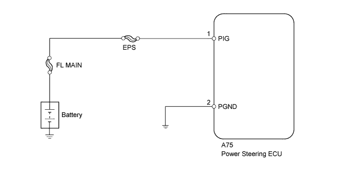
WIRING DIAGRAM
INSPECTION PROCEDURE
- NOTICE:
- If the power steering ECU has been replaced with a new one, perform the assist map writing and the torque sensor zero point calibration (Click here).
| 1.INSPECT FUSE (EPS FUSE) |
Remove the EPS fuse from the engine room relay block.
Measure the resistance according to the value(s) in the table below.
- Standard Resistance:
Fuse Condition Specified Condition EPS fuse Always Below 1 Ω
|
| ||||
| OK | |
| 2.CHECK HARNESS AND CONNECTOR (BATTERY - POWER STEERING ECU - BODY GROUND) |
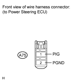
Disconnect the connector from the power steering ECU.
 |
Measure the voltage according to the value(s) in the table below.
- Standard Voltage:
Tester Connection Switch Condition Specified Condition A75-1 (PIG) - Body ground Ignition switch on (IG) 11 to 14 V
Measure the resistance according to the value(s) in the table below.
- Standard Resistance:
Tester Connection Condition Specified Condition A75-2 (PGND) - Body ground Always Below 1 Ω
|
| ||||
| OK | ||
| ||