ENGINE ASSEMBLY > REMOVAL |

for Preparation Click here
| 1. DISCHARGE FUEL SYSTEM PRESSURE |
- HINT:
| 2. ALIGN FRONT WHEELS FACING STRAIGHT AHEAD |
| 3. DISCONNECT CABLE FROM NEGATIVE BATTERY TERMINAL |
| 4. REMOVE FRONT WHEELS |
| 5. REMOVE ENGINE UNDER COVER LH |
| 6. REMOVE ENGINE UNDER COVER RH |
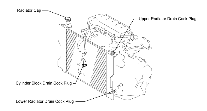
| 7. DRAIN ENGINE COOLANT |
Loosen the lower radiator drain cock plug.
- CAUTION:
- Do not loosen the lower radiator drain cock plug while the engine and radiator are still hot.
- Pressurized, hot engine coolant and steam may be released and cause serious burns.
- HINT:
- Collect the coolant in a container and dispose of it according to the regulations in your area.
Remove the radiator cap.
Loosen the cylinder block drain cock plug.
| 8. DRAIN AUTOMATIC TRANSAXLE FLUID (for Automatic Transaxle) |
- HINT:
- Click here for U250E.
| 9. DRAIN MANUAL TRANSAXLE OIL (for Manual Transaxle) |
- HINT:
- Click here for E351.
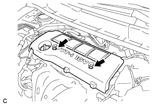
| 10. REMOVE NO. 1 ENGINE COVER SUB-ASSEMBLY |
Remove the 2 nuts and No. 1 engine cover sub-assembly.
 |
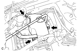
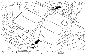
| 11. SEPARATE RADIATOR RESERVE TANK ASSEMBLY |
Remove the 3 bolts and separate the radiator reserve tank assembly.
 |
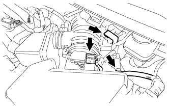
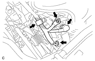
| 12. REMOVE AIR CLEANER CAP SUB-ASSEMBLY WITH HOSE |
Disconnect the mass air flow meter connector.
 |
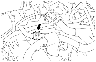
Separate the 2 wire harness clamps.
Disconnect the No. 1 vacuum switching valve connector and the 2 vacuum hoses.
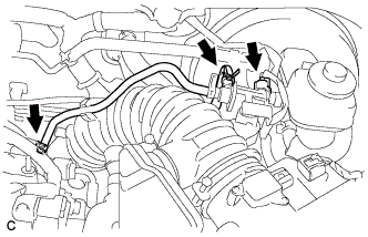 |
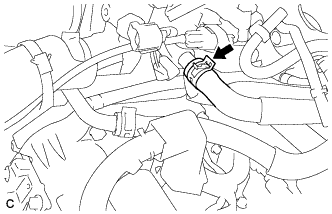
Disconnect the ventilation hose.
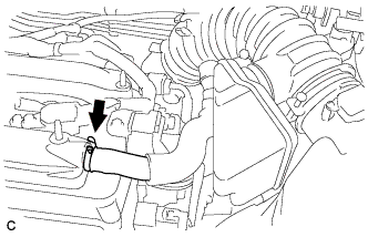 |
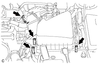
Loosen the No. 1 air cleaner hose clamp, release the 3 air cleaner assembly clamps and remove the air cleaner cap sub-assembly with No. 1 hose.
 |
| 13. REMOVE AIR CLEANER CASE |
Remove the air cleaner filter element.
Disconnect the clamp of the engine wire.
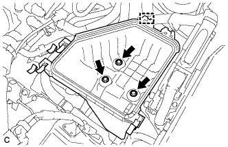 |
Remove the 3 bolts and air cleaner case.
| 14. REMOVE BATTERY |
Remove the bolt, nut and battery clamp.
 |
Remove the battery and battery insulator.
| 15. REMOVE BATTERY CARRIER |
Remove the battery tray.
Separate the 2 wire harness clamps from the battery carrier.
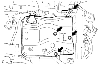 |
Remove the 4 bolts and battery carrier.
| 16. SEPARATE WIRE HARNESS |
Disconnect the 3 connectors from the engine room relay block.
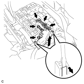 |
Remove the 2 nuts and disconnect the wire harnesses from the engine room relay block.
Using a screwdriver, unlock the 2 claws.
Pull the engine room relay block upward.
Pull up the lever and disconnect the ECM connector.
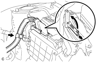 |
Disconnect the clamp.
Remove the bolt and disconnect the ground cable and clamp (for Manual Transaxle).
 |
Remove the bolt and disconnect the ground cable and clamp (for Automatic Transaxle).
 |
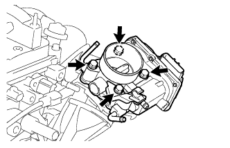
| 17. REMOVE THROTTLE BODY ASSEMBLY |
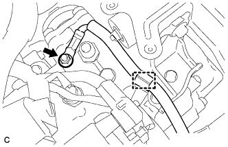
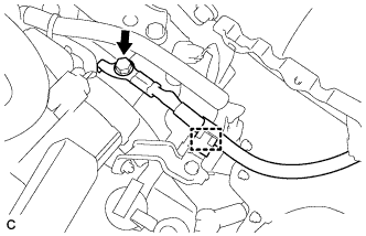
Disconnect the 2 water by-pass hoses.
 |
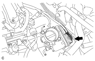
Disconnect the throttle body assembly connector.
 |
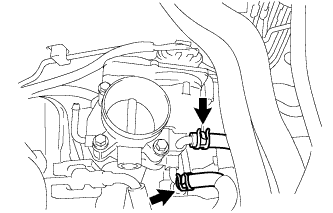
Remove the 4 bolts and throttle body assembly.
 |
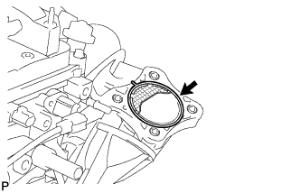
Remove the gasket from the intake manifold.
 |
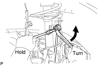
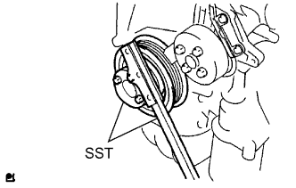
| 18. REMOVE V-RIBBED BELT |
Using SST, slowly turn the V-ribbed belt tensioner clockwise.
- SST
- 09216-42010
(09216-04010)
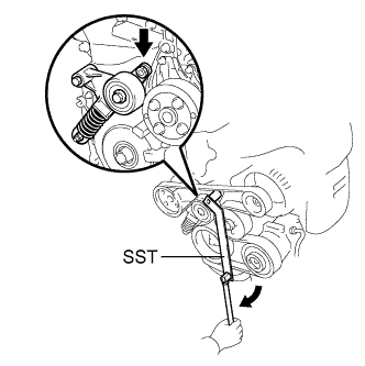 |
Remove the V-ribbed belt from each pulley and slowly return the tensioner.
- NOTICE:
- Make sure that SST and other tools are set to the tensioner securely.
- When compressing the V-ribbed belt tensioner, slowly turn the tensioner.
- Be careful not to pinch your fingers between the parts.
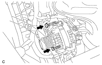
| 19. REMOVE GENERATOR ASSEMBLY |
Disconnect the generator connector.
 |
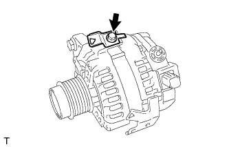
Remove the nut and disconnect the wire harness from terminal B.
Separate the 2 wire harness clamps.
Remove the 2 bolts and generator assembly.
 |
Remove the bolt and wire harness clamp bracket.
 |
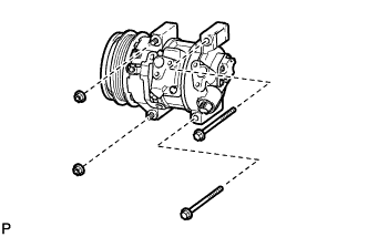
| 20. SEPARATE COMPRESSOR ASSEMBLY WITH PULLEY |
Disconnect the connector.
Remove the 2 bolts and 2 nuts.
 |
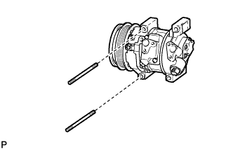
Using a "TORX" socket wrench (E8), remove the 2 stud bolts and compressor with pulley assembly.
- HINT:
- Secure the compressor and hoses off to the side instead of discharging the A/C system.
 |
| 21. DISCONNECT NO. 2 RADIATOR HOSE |
Disconnect the No. 2 radiator hose from the inlet water.
 |
| 22. DISCONNECT NO. 1 RADIATOR HOSE |
Disconnect the No. 1 radiator hose from the cylinder head.
 |
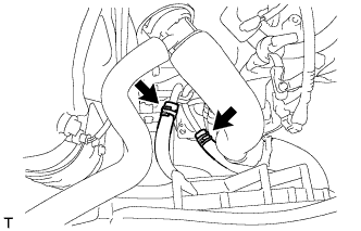
| 23. DISCONNECT OIL COOLER HOSE (for Automatic Transaxle) |
Disconnect the 2 oil cooler hoses.
 |
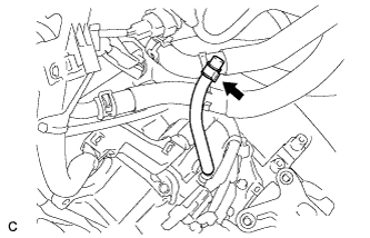
| 24. DISCONNECT BREATHER HOSE (for Automatic Transaxle) |
Disconnect the breather hose.
 |
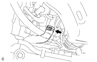
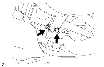
| 25. DISCONNECT OUTLET HEATER WATER HOSE |
Disconnect the outlet heater water hose.
 |
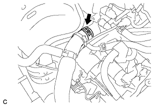
| 26. DISCONNECT INLET HEATER WATER HOSE |
Disconnect the inlet heater water hose.
 |
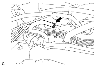
| 27. REMOVE FUEL TUBE SUB-ASSEMBLY |
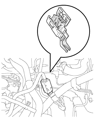
Release the claw and remove the No. 1 fuel pipe clamp.
 |
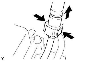
Pinch the retainer as illustrated, then pull the fuel tube connector out of the pipe.
- NOTICE:
- Remove any dirt or foreign matter from the fuel tube connector before performing this work.
- Do not allow any scratches or foreign matter on the parts when disconnecting, as the fuel tube connector has O-rings that seal the pipe.
- Perform this work by hand. Do not use any tools.
- Do not forcibly bend, kink or twist the nylon tube.
- Protect the disconnected parts by covering them with vinyl bags after disconnecting the fuel tube.
- If the fuel tube connector and pipe are stuck, push and pull to release them.
 |
| 28. DISCONNECT UNION TO CONNECTOR TUBE HOSE |
Disconnect the union to connector tube hose.
 |
| 29. SEPARATE CLUTCH RELEASE CYLINDER ASSEMBLY (for Manual Transaxle) |
- HINT:
- Click here for E351.
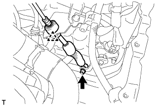
| 30. SEPARATE TRANSMISSION CONTROL CABLE ASSEMBLY (for Automatic Transaxle) |
Remove the nut and disconnect the control cable assembly from the control shaft lever.
 |
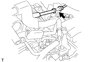
Remove the clip and disconnect the transmission control cable assembly from the control cable bracket.
Disconnect the control cable assembly from the control cable bracket.
 |
| 31. SEPARATE TRANSMISSION CONTROL CABLE ASSEMBLY (for Manual Transaxle) |
Remove the 2 clips and disconnect the 2 transmission control cables from the control cable bracket*1.
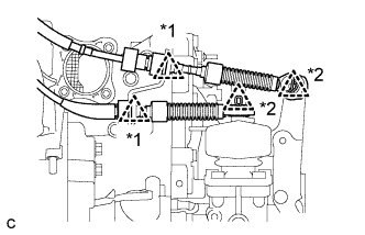 |
Remove the 2 clips and disconnect the 2 transmission control cables from the transaxle*2.
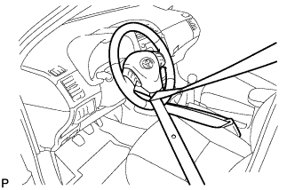
| 32. SECURE STEERING WHEEL |
Secure the steering wheel with the seat belt in order to prevent rotation.
- HINT:
- This operation is useful to prevent damage to the spiral cable.
 |
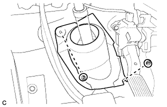
| 33. REMOVE COLUMN HOLE COVER SILENCER SHEET |
Turn back the floor carpet, and remove the 2 clips and column hole cover silencer sheet.
 |
| 34. SEPARATE NO. 2 STEERING INTERMEDIATE SHAFT ASSEMBLY |
Put matchmarks on the No. 2 steering intermediate shaft assembly and the steering intermediate shaft.
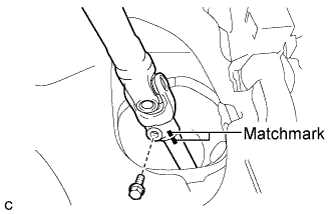 |
Remove the bolt and separate the No. 2 steering intermediate shaft assembly from the steering intermediate shaft.
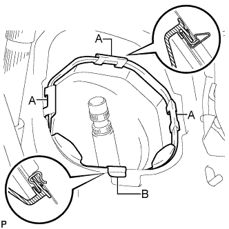
| 35. SEPARATE NO. 1 STEERING COLUMN HOLE COVER SUB-ASSEMBLY |
Remove clips A and the No. 1 steering column hole cover sub-assembly and disengage clip B from the body.
- NOTICE:
- Do not damage clips A and B.
 |
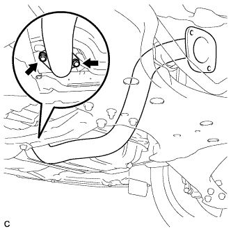
| 36. REMOVE CENTER EXHAUST PIPE ASSEMBLY |
Remove the 4 bolts and 2 compression springs.
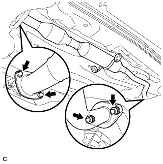 |
Remove the center exhaust pipe assembly from the 2 exhaust pipe supports.
Remove the 2 gaskets.
| 37. REMOVE FRONT EXHAUST PIPE ASSEMBLY |
Disconnect the heated oxygen sensor connector.
 |
Remove the 2 bolts, 2 compression springs and front exhaust pipe assembly.
Remove the gasket from the exhaust manifold.
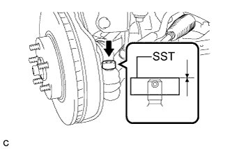
| 38. REMOVE FRONT AXLE SHAFT NUT LH |
Using SST and a hammer, release the staked part of the front axle shaft nut LH.
- SST
- 09930-00010
- NOTICE:
- Insert SST into the groove with the flat surface facing up.
- Do not damage the tip of SST using grinders.
- Completely unstake the staked part before removing the axle hub nut.
- Do not damage the threads of the drive shaft.
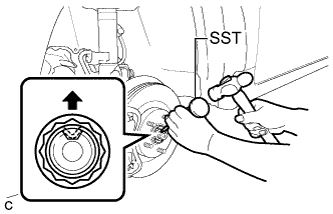 |
Using a socket wrench (30 mm), remove the front axle shaft nut LH.
| 39. REMOVE FRONT AXLE SHAFT NUT RH |
- HINT:
- Perform the same procedure for the LH side.
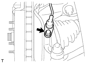
| 40. SEPARATE FRONT SPEED SENSOR LH |
Remove the bolt and separate the front speed sensor and flexible hose from the front shock absorber bracket.
 |
Remove the bolt and separate the front speed sensor from the steering knuckle.
- NOTICE:
- Keep the front speed sensor tip and installation surfaces free of foreign matter.
- Remove the front speed sensor without turning it from its original installation angle.
 |
| 41. SEPARATE FRONT SPEED SENSOR RH |
- HINT:
- Perform the same procedure for the LH side.
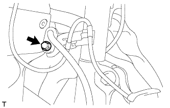
| 42. SEPARATE TIE ROD END SUB-ASSEMBLY LH |
Remove the cotter pin and the nut.
Install SST to the tie rod end.
- SST
- 09960-20010
(09961-02060)
- NOTICE:
- Make sure that the upper ends of the tie rod end and SST are aligned.
 |
Using SST, separate the tie rod end from the steering knuckle.
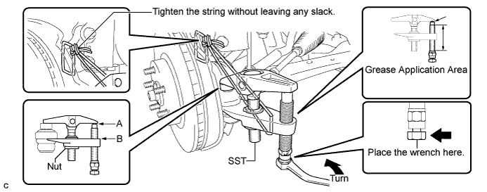
- SST
- 09960-20010
(09961-02010)
- CAUTION:
- Apply grease to the threads of the bolt and the tip of SST.
- NOTICE:
- Be sure to tighten the string firmly to secure SST to the steering knuckle to prevent SST from falling off.
- Install SST with the center nut so that A and B are parallel. Otherwise, the dust cover may be damaged.
- Be sure to place the wrench on the part indicated in the illustration.
- Do not damage the front disc brake dust cover.
- Do not damage the ball joint dust cover.
- Do not damage the steering knuckle.
| 43. SEPARATE TIE ROD END SUB-ASSEMBLY RH |
- HINT:
- Perform the same procedure for the LH side.
| 44. SEPARATE FRONT STABILIZER LINK ASSEMBLY LH |
Remove the nut and separate the stabilizer link assembly from the front shock absorber with coil spring.
- NOTICE:
- If the ball joint turns together with the nut, use a hexagon wrench (6 mm) to hold the stud bolt.
 |
| 45. SEPARATE FRONT STABILIZER LINK ASSEMBLY RH |
- HINT:
- Perform the same procedure for the LH side.
| 46. SEPARATE FRONT LOWER SUSPENSION ARM LH |
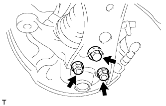
Remove the bolt and 2 nuts, and separate the front lower suspension arm from the lower ball joint.
 |
| 47. SEPARATE FRONT LOWER SUSPENSION ARM RH |
- HINT:
- Perform the same procedure for the LH side.
| 48. SEPARATE STEERING KNUCKLE WITH AXLE HUB LH |
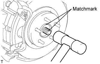
Put matchmarks on the drive shaft and axle hub.
- NOTICE:
- Do not punch the marks.
 |
Using a plastic-faced hammer, disconnect the front axle assembly LH.
- NOTICE:
- Be careful not to damage the boot or speed sensor rotor.
- Do not excessively push out the drive shaft from the axle assembly.
| 49. SEPARATE STEERING KNUCKLE WITH AXLE HUB RH |
- HINT:
- Perform the same procedure for the LH side.
| 50. REMOVE FRONT DRIVE SHAFT ASSEMBLY LH |
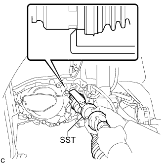
Using SST, remove the front drive shaft assembly LH.
- SST
- 09520-01010
09520-24010 (09520-32040)
- NOTICE:
- Do not damage the oil seal.
- Do not damage the inboard joint boot.
- Do not drop the drive shaft.
 |
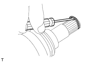
| 51. REMOVE FRONT DRIVE SHAFT HOLE SNAP RING LH |
Using a screwdriver, remove the snap ring from the front drive inboard joint assembly.
 |
| 52. REMOVE FRONT DRIVE SHAFT ASSEMBLY RH |
Remove the bearing bracket hole snap ring.
 |
Remove the bolt and front drive shaft assembly RH from the drive shaft bearing bracket.
- NOTICE:
- Do not damage the boot or oil seal.
| 53. REMOVE DRIVE PLATE AND TORQUE CONVERTER ASSEMBLY SETTING BOLT (for Automatic Transaxle) |
- HINT:
- Click here for U250E.
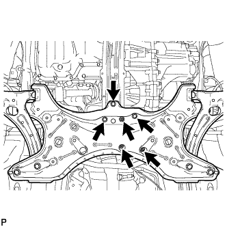
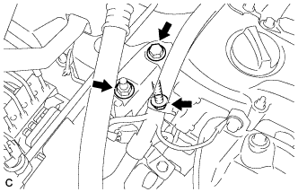
| 54. REMOVE FRONT SUSPENSION CROSSMEMBER SUB-ASSEMBLY |
Remove the 3 bolts and 3 nuts.
 |
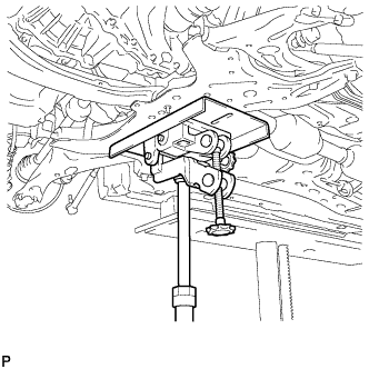
Using a transmission jack or equivalent, support the front suspension crossmember sub-assembly.
 |
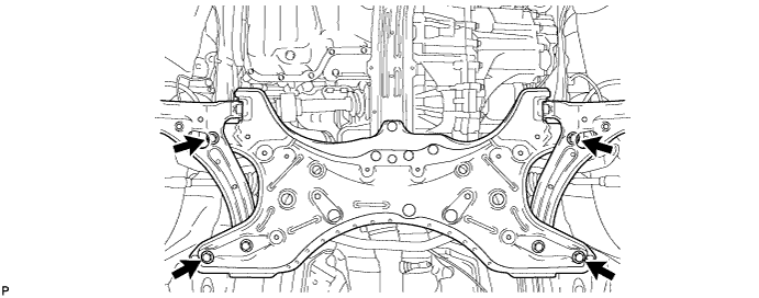
Remove the 4 bolts and front suspension crossmember sub-assembly.
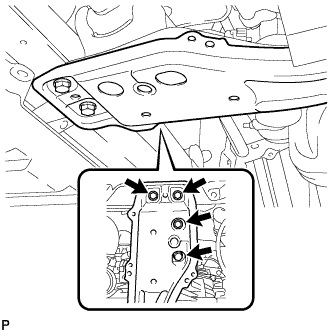
| 55. REMOVE CENTER ENGINE MOUNTING MEMBER SUB-ASSEMBLY |
Remove the 4 bolts and center engine mounting member sub-assembly.
 |
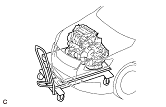
| 56. REMOVE ENGINE ASSEMBLY WITH TRANSAXLE |
Set the engine assembly with transaxle on the engine lifter.
- NOTICE:
- Place the engine on wooden blocks or equivalent so that the engine is level.
 |
Remove the bolt and 2 nuts, and separate the engine mounting insulator RH.
 |
Remove the through bolt and nut, and separate the engine mounting insulator LH.
 |
Carefully remove the engine with transaxle from the vehicle.
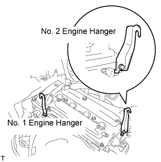
| 57. INSTALL ENGINE HANGERS |
Install the No. 1 and No. 2 engine hangers with new bolts as shown in the illustration.
- Torque:
- 38 N*m{ 387 kgf*cm , 28 ft.*lbf }
Item Part No. No. 1 engine hanger 12281-28010 No. 2 engine hanger 12282-28010 or 12282-AB010 Bolt 90080-10177
 |
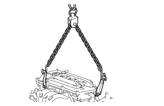
Using an engine sling device and a chain block, suspend the engine assembly with transaxle.
 |
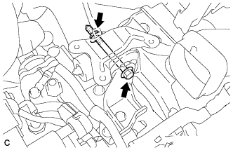
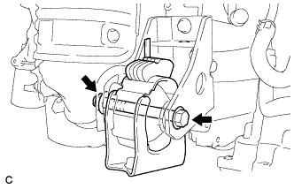
| 58. REMOVE FRONT ENGINE MOUNTING INSULATOR |
Remove the through bolt and nut, and separate the front engine mounting insulator.
 |
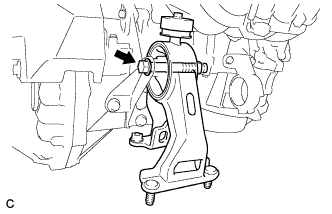
| 59. REMOVE REAR ENGINE MOUNTING INSULATOR |
Remove the through bolt and separate the rear engine mounting insulator.
 |
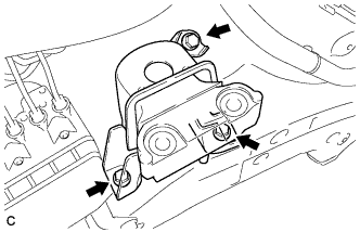
| 60. REMOVE ENGINE MOUNTING INSULATOR LH |
Remove the 4 bolts and engine mounting insulator LH.
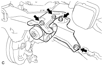 |
| 61. REMOVE ENGINE MOUNTING INSULATOR SUB-ASSEMBLY RH |
Remove the 3 bolts and engine mounting insulator sub-assembly RH.
 |
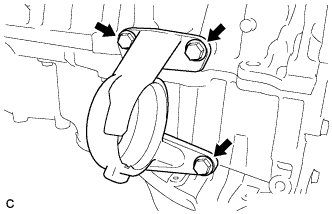
| 62. REMOVE DRIVE SHAFT BEARING BRACKET |
Remove the 3 bolts and bracket.
 |
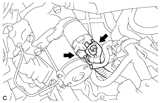
| 63. REMOVE STARTER ASSEMBLY (for Automatic Transaxle) |
Disconnect the terminal 50 connector from the starter assembly.
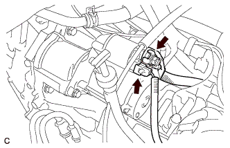 |
Remove the nut and disconnect the wire harness from terminal 30.
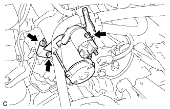
Remove the 2 bolts, wire harness clamp bracket and starter assembly.
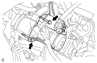 |
| 64. REMOVE STARTER ASSEMBLY (for Manual Transaxle) |
Disconnect the terminal 50 connector from the starter assembly.
 |
Remove the nut and disconnect the wire harness from terminal 30.
Remove the 3 bolts, clutch accumulator bracket, wire harness clamp bracket and starter assembly.
 |
| 65. REMOVE MANUAL TRANSAXLE ASSEMBLY (for Manual Transaxle) |
- HINT:
- Click here for E351.
| 66. REMOVE AUTOMATIC TRANSAXLE ASSEMBLY (for Automatic Transaxle) |
- HINT:
- Click here for U250E.
| 67. REMOVE CLUTCH COVER ASSEMBLY (for Manual Transaxle) |
- HINT:
- Click here for E351.
| 68. REMOVE CLUTCH DISC ASSEMBLY (for Manual Transaxle) |
- HINT:
- Click here for E351.
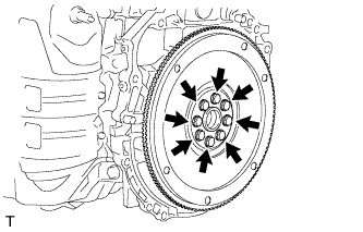
| 69. REMOVE FLYWHEEL SUB-ASSEMBLY (for Manual Transaxle) |
Using SST, hold the crankshaft.
- SST
- 09213-54015
(91651-60855)
09330-00021
 |
Remove the 8 bolts and flywheel.
 |
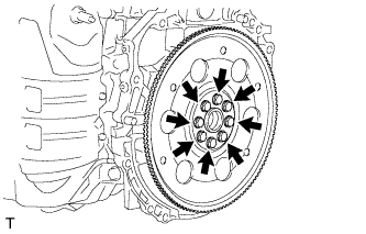
| 70. REMOVE DRIVE PLATE AND RING GEAR SUB-ASSEMBLY (for Automatic Transaxle) |
Using SST, hold the crankshaft.
- SST
- 09213-54015
(91651-60855)
09330-00021
|
Remove the 8 bolts, rear drive plate spacer, drive plate and front drive plate spacer.
 |
| 71. REMOVE ENGINE WIRE |