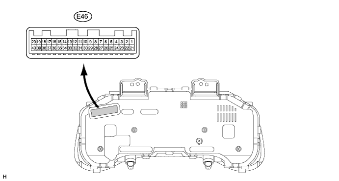
Terminal No. (Symbol)
| Wiring Color
| Terminal Description
| Condition
| Specified Condition
|
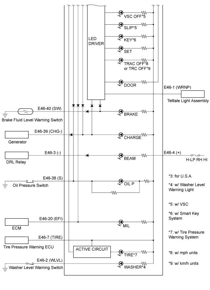
E46-1 (WRNP) - Body ground
| BE*1 or W*2 - Body ground
| Front passenger side seat belt warning light signal
| Front passenger seat occupied, ignition switch ON, front passenger side seat belt warning light OFF
| 11 to 14 V
|
Front passenger seat occupied, ignition switch ON, front passenger side seat belt warning light is blinking
| Below 1 V ←→ 11 to 14 V
|
E46-2 (WLVL)*3 - Body ground
| BE - Body ground
| Washer level warning light signal
| Ignition switch ON, washer level warning light OFF
| 11 to 14 V
|
Ignition switch ON, washer level warning light ON
| Below 1 V
|
E46-3 (-) - Body ground
| L*2 or *5, W-B*6 - Body ground
| Headlight Hi-beam indicator light signal
| Always
| Below 1 V
|
E46-4 (+) - Body ground
| R - Body ground
| Headlight Hi-beam indicator light signal
| Hi-beam switch OFF
| 11 to 14 V
|
Hi-beam switch ON
| Below 1 V
|
E46-5 (B) - Body ground
| L - Body ground
| Turn indicator light signal
| Ignition switch ON, turn signal RH indicator light OFF
| Below 1 V
|
Ignition switch ON, turn signal RH indicator light ON
| 11 to 14 V
|
E46-6 (B) - Body ground
| Y - Body ground
| Turn indicator light signal
| Ignition switch ON, turn signal LH indicator light OFF
| Below 1 V
|
Ignition switch ON, turn signal LH indicator light ON
| 11 to 14 V
|
E46-7 (TIRE) - Body ground
| P - Body ground
| Tire pressure warning light signal
| Ignition switch ON, tire pressure warning light OFF
| 3.2 V or more
|
Ignition switch ON, tire pressure warning light ON
| 0.9 to 3.2 V
|
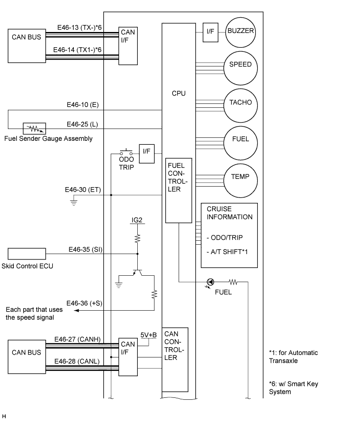
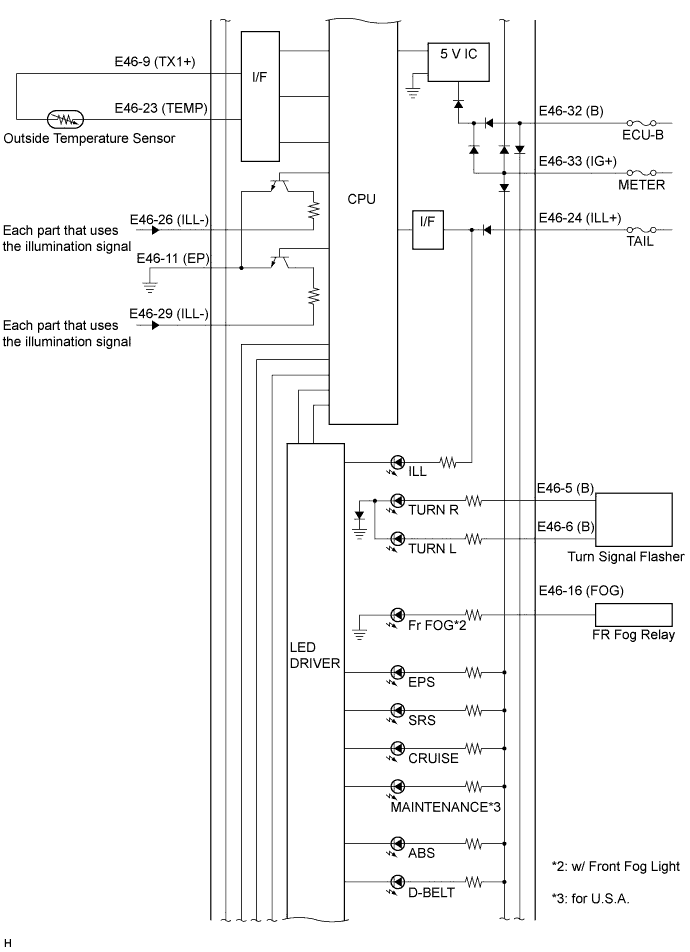
E46-9 (TX1+) - Body ground
| G*1 or LG*2 - Body ground
| Outside temperature signal
| Ignition switch ON
| 5 V or less
|
E46-10 (E) - Body ground
| BR - Body ground
| Ground (Fuel ground)
| Always
| Below 1 V
|
E46-11 (EP) - Body ground
| W-B - Body ground
| Ground (Illumination ground)
| Always
| Below 1 V
|
E46-13 (TX-)*7 - Body ground
| W - Body ground
| CAN communication signal
| Ignition switch ON
| Pulse generation
|
E46-14 (TX1-)*7 - Body ground
| G - Body ground
| CAN communication signal
| Ignition switch ON
| Pulse generation
|
E46-16 (FOG)*4 - Body ground
| P - Body ground
| Front fog indicator light signal
| Front fog light switch off, front fog indicator light OFF
| Below 1 V
|
Front fog light switch on, front fog indicator light ON
| 11 to 14 V
|
E46-20 (EFI) - Body ground
| P*1 or R*2 - Body ground
| MIL (Check engine warning light) signal
| Ignition switch ON, MIL OFF
| 11 to 14 V
|
Ignition switch ON, MIL ON
| Below 3 V
|
E46-23 (TEMP) - Body ground
| W*1 or GR*2 - Body ground
| Outside temperature signal
| Ignition switch ON, outside temperature 25°C (77°F)
| Approximately 1.3 V
|
E46-24 (ILL+) - Body ground
| V*1 or G*2 - Body ground
| Tail indicator light signal
| Headlight dimmer switch off, tail indicator light OFF
| Below 1 V
|
Headlight dimmer switch is at the TAIL position, tail indicator light ON
| 11 to 14 V
|
E46-25 (L) - Body ground
| Y*1 or P*2 - Body ground
| Fuel signal
| Ignition switch ON, fuel level is EMPTY
| 3 to 7 V
|
Ignition switch ON, fuel level is FULL
| Below 1 V
|
E46-26 (ILL-) - Body ground
| V*5 or W*2 - Body ground
| Illumination signal
| Ignition switch ON, headlight dimmer switch OFF
| Below 1 V
|
Ignition switch ON, headlight dimmer switch is at the TAIL or HEAD position
| Below 1 V ←→ 11 to 14 V
|
E46-27 (CANH) - E46-28 (CANL)
| G - W
| CAN communication signal
| Ignition switch ON
| Pulse generation
|
E46-28 (CANL) - E46-27 (CANH)
| W - G
| CAN communication signal
| Ignition switch ON
| Pulse generation
|
E46-29 (ILL-) - Body ground
| BE*5 or W*2 - Body ground
| Illumination signal
| Ignition switch ON, headlight dimmer switch OFF
| Below 1 V
|
Ignition switch ON, headlight dimmer switch TAIL or HEAD position
| Below 1 V ←→ 11 to 14 V
|
E46-30 (ET) - Body ground
| BR*1 or W-B*2 - Body ground
| Ground (Signal ground)
| Always
| Below 1 V
|
E46-32 (B) - Body ground
| W*1 or R*2 - Body ground
| Battery
| Always
| 11 to 14 V
|
E46-33 (IG+) - Body ground
| P*1 or B*2 - Body ground
| Ignition switch signal
| Ignition switch off
| Below 1 V
|
Ignition switch ON
| 11 to 14 V
|
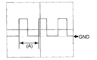
E46-35 (SI) - Body ground
| V*1 or LG*2 - Body ground
| Speed signal for other systems (Input)
| Ignition switch ON, wheel turned slowly
| Pulse generation
(See waveform)
|
E46-36 (+S) - Body ground
| V - Body ground
| Speed signal for other systems (Output)
| Wheel turned slowly
| Pulse generation
(See waveform)
|
E46-38 (S) - Body ground
| Y*1 or G*2 - Body ground
| Engine oil pressure warning light signal
| Ignition switch ON, engine oil pressure warning light OFF
| 11 to 14 V
|
Ignition switch ON, engine oil pressure warning light ON
| Below 1 V
|
E46-39 (CHG-) - Body ground
| Y - Body ground
| Charge warning light signal
| Ignition switch ON, charge warning light OFF
| 11 to 14 V
|
Ignition switch ON, charge warning light ON
| Below 1 V
|
E46-40 (SW) - Body ground
| Y*1 or BE*2 - Body ground
| Brake fluid level warning light signal
| Ignition switch ON, brake warning light OFF
| 11 to 14 V
|
Ignition switch ON, brake warning light ON
| Below 1 V
|