DTC B1771 Passenger Side Buckle Switch Circuit Malfunction |

for Preparation Click here
DESCRIPTION
The passenger side buckle switch circuit consists of the occupant classification ECU and the front seat inner belt assembly RH.DTC B1771 is recorded when a malfunction is detected in the passenger side buckle switch circuit.
| DTC No. | DTC Detecting Condition | Trouble Area |
| B1771 |
|
|
- HINT:
- When DTC B1650/32 is detected as a result of troubleshooting for the airbag system, check the DTCs stored in the occupant classification ECU. When DTC B1771 is output, perform troubleshooting for the DTC.
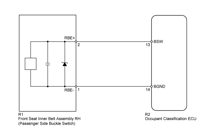
WIRING DIAGRAM
INSPECTION PROCEDURE
- HINT:
- If troubleshooting (wire harness inspection) is difficult to perform, remove the front passenger seat installation bolts to access the underside of the seat cushion.
- In the above case, hold the seat so that it does not fall down. Holding the seat for a long period of time may damage the seat or deform the seat rails. Hold the seat only as necessary.
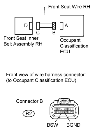
| 1.CHECK CONNECTORS |
Turn the ignition switch off.
Disconnect the cable from the negative (-) battery terminal.
Check that the connectors are properly connected to the occupant classification ECU and the front seat inner belt assembly RH.
- OK:
- The connectors are properly connected.
- HINT:
- If the connectors are not connected securely, reconnect the connectors and proceed to the next inspection.
Disconnect the connectors from the occupant classification ECU and the front seat inner belt assembly RH.
Check that the terminals of the connectors are not damaged.
- OK:
- The terminals are not deformed or damaged.
|
| ||||
| OK | |
| 2.CHECK FRONT SEAT WIRE RH (SHORT TO B+) |
Connect the cable to the negative (-) battery terminal.
 |
Turn the ignition switch to ON.
Measure the voltage according to the value(s) in the table below.
- Standard Voltage:
Tester Connection Switch Condition Specified Condition R2-13 (BSW) - Body ground Ignition switch ON Below 1 V R2-14 (BGND) - Body ground Ignition switch ON Below 1 V
|
| ||||
| OK | |
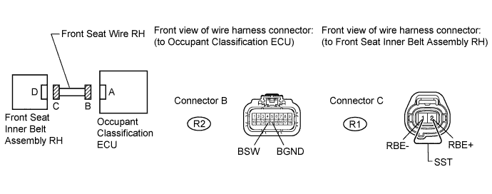
| 3.CHECK FRONT SEAT WIRE RH (OPEN) |
Turn the ignition switch off.
Disconnect the cable from the negative (-) battery terminal.
Using SST, connect terminals 2 (RBE+) and 1 (RBE-) of connector C.
- NOTICE:
- Do not forcibly insert SST into the terminals of the connector when connecting the wire.
- SST
- 09843-18040
Measure the resistance according to the value(s) in the table below.
- Standard Resistance:
Tester Connection Condition Specified Condition R2-13 (BSW) - R2-14 (BGND) Always Below 1 Ω
|
| ||||
| OK | |
| 4.CHECK FRONT SEAT WIRE RH (SHORT TO GROUND) |
Disconnect SST wire from connector C.
|
Measure the resistance according to the value(s) in the table below.
- Standard Resistance:
Tester Connection Condition Specified Condition R2-13 (BSW) - Body ground Always 1 MΩ or higher R2-14 (BGND) - Body ground Always 1 MΩ or higher
|
| ||||
| OK | |
| 5.CHECK FRONT SEAT WIRE RH (SHORT) |
Measure the resistance according to the value(s) in the table below.
- Standard Resistance:
Tester Connection Condition Specified Condition R2-13 (BSW) - R2-14 (BGND) Always 1 MΩ or higher
|
|
| ||||
| OK | |
| 6.CHECK FOR DTC |
Connect the connectors to the occupant classification ECU and the front seat inner belt assembly RH.
Connect the cable to the negative (-) battery terminal.
Turn the ignition switch to ON.
Clear the DTCs stored in the occupant classification ECU (Click here).
Clear the DTCs stored in the center airbag sensor assembly (Click here).
Turn the ignition switch off.
Turn the ignition switch to ON.
Check for DTCs (Click here).
- OK:
- DTC B1771 is not output.
- HINT:
- Codes other than B1771 may be output at this time, but they are not related to this check.
|
| ||||
| OK | ||
| ||
| 7.INSPECT FRONT SEAT INNER BELT ASSEMBLY RH |
Turn the ignition switch off.
Disconnect the cable from the negative (-) battery terminal.
Replace the front seat inner belt assembly RH with a known good part (Click here).
- HINT:
- Perform an inspection using known good parts from another vehicle if possible.
Connect the cable to the negative (-) battery terminal.
Turn the ignition switch to ON.
Clear the DTCs stored in the occupant classification ECU (Click here).
Clear the DTCs stored in the center airbag sensor assembly (Click here).
Turn the ignition switch off.
Turn the ignition switch to ON.
Check for DTCs (Click here).
- OK:
- DTC B1771 is not output.
- HINT:
- Codes other than B1771 may be output at this time, but they are not related to this check.
|
| ||||
| OK | ||
| ||
| 8.REPLACE OCCUPANT CLASSIFICATION ECU |
Connect the Techstream to the DLC3.
Turn the ignition switch to ON.
Using the Techstream, save the ECU data from the ECU currently installed on the vehicle (Click here).
Turn the ignition switch off.
Disconnect the cable from the negative (-) battery terminal.
Replace the occupant classification ECU (Click here).
Connect the cable to the negative (-) battery terminal.
Turn the ignition switch to ON.
Using the Techstream, load the previous ECU data stored into the new ECU (Click here).
Turn the ignition switch off.
Turn the ignition switch to ON.
Clear the DTCs stored in the memory (Click here).
- HINT:
- If the DTCs are not cleared at this time, past DTCs will remain.
| NEXT | |
| 9.PERFORM SENSITIVITY CHECK |
Perform the sensitivity check (Click here).
| NEXT | ||
| ||