REAR AXLE BEAM > INSTALLATION |

for Preparation Click here
| 1. INSTALL REAR AXLE CARRIER BUSHING LH |
Align the arrow mark on a new rear axle carrier bushing LH with the matchmark on the rear axle beam assembly and temporarily install the rear axle carrier bushing LH to the rear axle beam assembly. (Perform this procedure when reusing the rear axle beam assembly.)
- NOTICE:
- Install the rear axle carrier bushing LH in the same direction as the removed bushing.
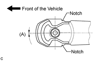 |
Temporarily install a new rear axle carrier bushing LH to the position shown in the illustration. (Perform this procedure when replacing with a new rear axle beam assembly.)
- (A):
- 0°53' +/- 3° (0.88° +/- 3°)
- NOTICE:
- Install the rear axle carrier bushing LH in the same direction as the removed bushing.
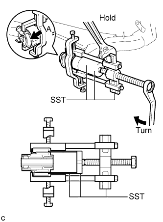
Using SST, install the rear axle carrier bushing LH to the rear axle beam assembly.
- SST
- 09710-30012
(09710-04101)
09950-40011 (09951-04020, 09952-04010, 09953-04030, 09954-04020, 09955-04051, 09957-04010, 09958-04011)
09950-60010 (09951-00620)
- NOTICE:
- Hang the claws of SST to the bushing deeply and firmly.
- Do not scratch the rubber portion (A) of the bushing.
- Do not deform the bushing rib.
 |
| 2. INSTALL REAR AXLE CARRIER BUSHING RH |
- HINT:
- Perform the same procedure as the LH side.
| 3. TEMPORARILY TIGHTEN REAR AXLE BEAM ASSEMBLY |
Support the rear axle beam assembly using 2 jacks and 2 wooden blocks.
 |
Temporarily install the rear axle beam assembly with the 2 bolts and 2 nuts.
 |
Temporarily tighten the 2 bolts.
- NOTICE:
- Since stopper nuts are used, temporarily tighten the bolts.
| 4. TEMPORARILY TIGHTEN REAR SHOCK ABSORBER WITH COIL SPRING LH |
Temporarily install the rear shock absorber with coil spring LH and the rear No. 1 shock absorber cushion retainer with the nut.
 |
| 5. TEMPORARILY TIGHTEN REAR SHOCK ABSORBER WITH COIL SPRING RH |
- HINT:
- Perform the same procedure as the LH side.
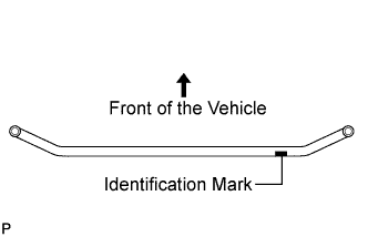
| 6. INSTALL REAR STABILIZER BAR (for TMC Made) |
Check that the identification mark of the rear stabilizer bar is positioned on the right side of the vehicle.
 |
Install the rear stabilizer bar with the 2 bolts and 2 nuts.
- Torque:
- 250 N*m{ 2549 kgf*cm , 184 ft.*lbf }
- NOTICE:
- Be sure to tighten the nuts.
- If reusing the bolts, insert them from the upper side of the vehicle.
 |
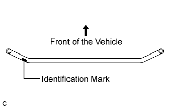
| 7. INSTALL REAR STABILIZER BAR (except TMC Made) |
Check that the identification mark of the rear stabilizer bar is positioned on the left side of the vehicle.
 |
Install the rear stabilizer bar with the 2 bolts and 2 nuts.
- Torque:
- 250 N*m{ 2549 kgf*cm , 184 ft.*lbf }
- NOTICE:
- Be sure to tighten the nuts.
- If reusing the bolts, insert them from the upper side of the vehicle.
|
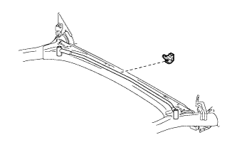
| 8. INSTALL REAR AXLE BEAM DAMPER |
Install the rear axle beam damper to the center of the rear stabilizer bar.
 |
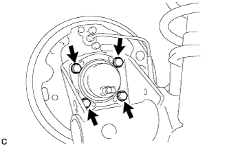
| 9. INSTALL REAR AXLE HUB AND BEARING ASSEMBLY LH (for Rear Drum Brake) |
Install the rear axle hub and bearing assembly with the 4 bolts.
- Torque:
- 100 N*m{ 1020 kgf*cm , 74 ft.*lbf }
 |
| 10. INSTALL REAR AXLE HUB AND BEARING ASSEMBLY RH (for Rear Drum Brake) |
- HINT:
- Perform the same procedure as the LH side.
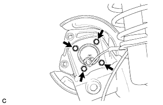
| 11. INSTALL REAR AXLE HUB AND BEARING ASSEMBLY LH (for Rear Disc Brake) |
Install the rear axle hub and bearing assembly with the 4 bolts.
- Torque:
- 100 N*m{ 1020 kgf*cm , 74 ft.*lbf }
 |
| 12. INSTALL REAR AXLE HUB AND BEARING ASSEMBLY RH (for Rear Disc Brake) |
- HINT:
- Perform the same procedure as the LH side.
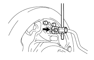
| 13. TEMPORARILY TIGHTEN NO. 4 REAR BRAKE TUBE (for Rear Drum Brake) |
Using a union nut wrench (10 mm), temporarily install the No. 4 rear brake tube to the rear brake wheel cylinder assembly LH.
- NOTICE:
- Do not bend or damage the brake line.
- Do not allow any foreign matter such as dirt and dust to enter the brake line.
 |
| 14. TEMPORARILY TIGHTEN NO. 3 REAR BRAKE TUBE (for Rear Drum Brake) |
- HINT:
- Perform the same procedure as the No. 4 rear brake tube.
| 15. INSTALL REAR FLEXIBLE HOSE LH (for Rear Drum Brake) |
Install the rear flexible hose LH with a new clip.
- NOTICE:
- Install the new clip as far as it will go.
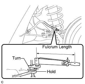
Using a union nut wrench (10 mm), connect the No. 4 rear brake tube to the rear flexible hose while holding the rear flexible hose LH with a wrench.
- Torque:
- without union nut wrench:
- 15 N*m{ 155 kgf*cm , 11 ft.*lbf }
- with union nut wrench:
- 14 N*m{ 143 kgf*cm , 10 ft.*lbf }
- NOTICE:
- Do not bend or damage the brake line.
- Do not allow any foreign matter such as dirt and dust to enter the brake line.
- Use a torque wrench with a fulcrum length of 250 mm (9.84 in.).
- This torque value is effective when the union nut wrench is parallel to the torque wrench.
 |
| 16. INSTALL REAR FLEXIBLE HOSE RH (for Rear Drum Brake) |
- HINT:
- Perform the same procedure as the LH side.
| 17. FULLY TIGHTEN NO. 4 REAR BRAKE TUBE (for Rear Drum Brake) |
Using a union nut wrench (10 mm), fully tighten the No. 4 rear brake tube.
- Torque:
- without union nut wrench:
- 15 N*m{ 155 kgf*cm , 11 ft.*lbf }
- with union nut wrench:
- 14 N*m{ 143 kgf*cm , 10 ft.*lbf }
- NOTICE:
- Use a torque wrench with a fulcrum length of 250 mm (9.84 in.).
- This torque value is effective when the union nut wrench is parallel to the torque wrench.
 |
| 18. FULLY TIGHTEN NO. 3 REAR BRAKE TUBE (for Rear Drum Brake) |
- HINT:
- Perform the same procedure as the No. 4 rear brake tube.
| 19. INSTALL REAR DISC LH (for Rear Disc Brake) |
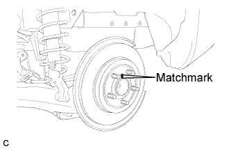
Align the matchmarks of the disc and axle hub and install the disc.
- NOTICE:
- When replacing the disc with a new one, select the installation position where the rear disc has minimal runout.
 |
| 20. INSTALL REAR DISC RH (for Rear Disc Brake) |
- HINT:
- Perform the same procedure as the LH side.
| 21. INSTALL REAR DISC BRAKE CALIPER ASSEMBLY LH (for Rear Disc Brake) |
Install the rear disc brake caliper assembly with the 2 bolts.
- Torque:
- 63 N*m{ 642 kgf*cm , 46 ft.*lbf }
 |
| 22. INSTALL REAR DISC BRAKE CALIPER ASSEMBLY RH (for Rear Disc Brake) |
- HINT:
- Perform the same procedure as the LH side.
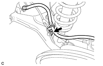
| 23. INSTALL REAR FLEXIBLE HOSE LH (for Rear Disc Brake) |
Install the rear flexible hose LH to the rear axle beam with the bolt.
- Torque:
- 29 N*m{ 296 kgf*cm , 21 ft.*lbf }
- NOTICE:
- Do not twist the rear flexible hose LH.
 |
| 24. INSTALL REAR FLEXIBLE HOSE RH (for Rear Disc Brake) |
- HINT:
- Perform the same procedure as the LH side.
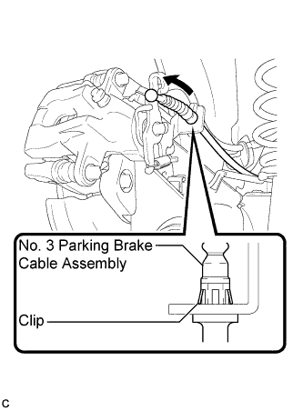
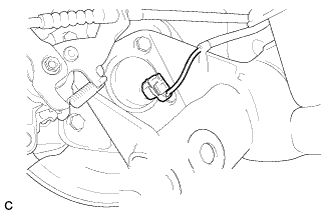
| 25. CONNECT NO. 3 PARKING BRAKE CABLE ASSEMBLY (for Rear Disc Brake) |
Install the No. 3 parking brake cable assembly to the rear disc brake cylinder assembly LH.
- HINT:
- Be sure to engage the No. 3 parking cable assembly clip onto the rear disc brake cylinder assembly LH as shown in the illustration.
 |
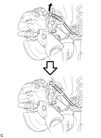
Connect the No. 3 parking brake cable assembly to the rear disc brake cylinder assembly LH.
 |
| 26. CONNECT NO. 2 PARKING BRAKE CABLE ASSEMBLY (for Rear Disc Brake) |
- HINT:
- Perform the same procedure as the No. 3 parking brake cable assembly side.
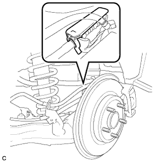
| 27. INSTALL PARKING BRAKE LEVER PROTECTOR LH (for Rear Disc Brake) |
Install the parking brake lever protector to the No. 3 parking brake cable assembly.
 |
| 28. INSTALL PARKING BRAKE LEVER PROTECTOR RH (for Rear Disc Brake) |
- HINT:
- Perform the same procedure as the LH side.
| 29. INSTALL REAR BRAKE DRUM LH (for Rear Drum Brake) |
Install the rear brake drum.
| 30. INSTALL REAR BRAKE DRUM RH (for Rear Drum Brake) |
- HINT:
- Perform the same procedure as the LH side.
| 31. INSTALL NO. 3 PARKING BRAKE CABLE ASSEMBLY |
Install the No. 3 parking brake cable assembly with the bolt.
- Torque:
- 6.0 N*m{ 61 kgf*cm , 53 in.*lbf }
 |
| 32. INSTALL NO. 2 PARKING BRAKE CABLE ASSEMBLY |
- HINT:
- Perform the same procedure as the No. 3 parking brake cable assembly.
| 33. INSTALL REAR SPEED SENSOR WIRE LH |
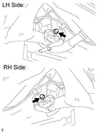
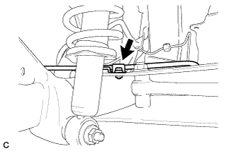
Install the rear speed sensor wire LH with the bolt.
- Torque:
- 8.0 N*m{ 82 kgf*cm , 71 in.*lbf }
- NOTICE:
- Do not twist the rear speed sensor wire LH.
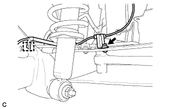 |
Engage the clamp.
- NOTICE:
- Do not twist the rear speed sensor wire LH.
| 34. INSTALL REAR SPEED SENSOR WIRE RH |
- HINT:
- Perform the same procedure as the LH side.
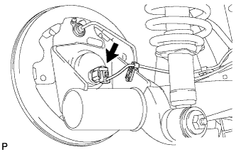
| 35. CONNECT REAR SPEED SENSOR WIRE LH (for Rear Drum Brake) |
Connect the rear speed sensor wire connector to the rear speed sensor.
 |
| 36. CONNECT REAR SPEED SENSOR WIRE RH (for Rear Drum Brake) |
- HINT:
- Perform the same procedure as the LH side.
| 37. CONNECT REAR SPEED SENSOR WIRE LH (for Rear Disc Brake) |
Connect the rear speed sensor wire connector to the rear speed sensor.
 |
| 38. CONNECT REAR SPEED SENSOR WIRE RH (for Rear Disc Brake) |
- HINT:
- Perform the same procedure as the LH side.
| 39. ADJUST PARKING BRAKE LEVER TRAVEL (for Rear Disc Brake) |
Remove the upper console box assembly (Click here).
Completely release the parking brake lever.
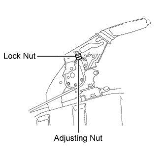
Loosen the lock nut and the adjusting nut to completely release the parking brake cable.
 |
Fully depress the brake lever 3 to 5 times with the engine stopped.
Turn the adjusting nut until the parking brake lever travel is corrected to within the specified range.
- Parking brake lever travel:
- 6 to 9 notches at 200 N (20 kgf, 45.0 lbf)
Using a wrench or an equivalent tool, hold the adjusting nut and tighten the lock nut.
- Torque:
- 6.0 N*m{ 61 kgf*cm , 53 in.*lbf }
Operate the parking brake lever 3 to 4 times, and check the parking brake lever travel.
Check whether the parking brake drags or not.
Install the upper console box assembly (Click here).
| 40. INSPECT REAR DISC BRAKE CYLINDER OPERATION LEVER AND STOPPER CLEARANCE (for Rear Disc Brake) |
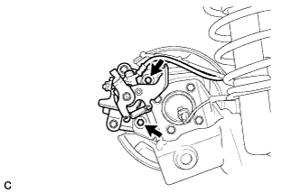
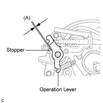
Release the parking brake lever and check that the clearance measurement between the rear disc brake cylinder operation lever and the stopper is within the specified range.
- Clearance (A):
- 0.5 mm (0.0197 in.) or less
 |
| 41. ADJUST REAR DRUM BRAKE SHOE CLEARANCE (for Rear Drum Brake) |
Temporarily install the 2 wheel nuts.
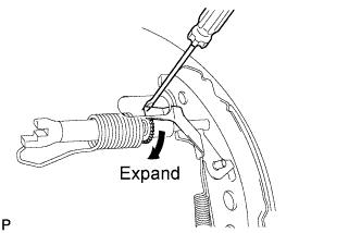 |
Remove the shoe adjusting hole plug, and turn the adjuster to expand the shoe until the drum locks.
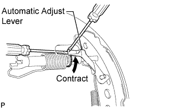
Hold the automatic adjust lever away from the adjuster, and contract the brake shoe by turning the adjust bolt using another screwdriver until the drum can rotate smoothly.
- Standard:
- 11 notches
 |
Install the hole plug.
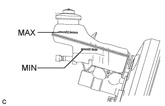
| 42. FILL BRAKE FLUID RESERVOIR (for Rear Drum Brake) |
Fill the reservoir with brake fluid.
- Brake Fluid:
- SAE J1703 or FMVSS No. 116 DOT 3
- NOTICE:
- Add brake fluid to keep the level between the MIN and MAX lines of the reservoir while bleeding the brakes.
| 43. BLEED BRAKE LINE (for Rear Drum Brake) |
- NOTICE:
- Bleed the brake line of the wheel farthest from the master cylinder first.
- Add brake fluid to keep the level between the MIN and MAX lines of the reservoir while bleeding the brakes.
Connect a vinyl tube to the bleeder plug.
Depress the brake pedal several times, and then loosen the bleeder plug with the pedal depressed*1.
When fluid stops coming out, tighten the bleeder plug, and then release the brake pedal*2.
Repeat *1 and *2 until all the air in the fluid is completely bled out.
Tighten the bleeder plug completely.
- Torque:
- Front bleeder plug:
- 8.3 N*m{ 85 kgf*cm , 73 in.*lbf }
- Rear bleeder plug (for Drum Brake):
- 8.5 N*m{ 87 kgf*cm , 75 in.*lbf }
- Rear bleeder plug (for Disc Brake):
- 10 N*m{ 102 kgf*cm , 7 ft.*lbf }
Repeat the above procedure for each wheel to bleed the brake line.
| 44. INSPECT FOR BRAKE FLUID LEAK (for Rear Drum Brake) |
| 45. INSPECT BRAKE FLUID LEVEL (for Rear Drum Brake) |
Check the fluid level.
If brake fluid level is lower than the MIN line, check for leaks and inspect the disc brake pads. If necessary, refill the reservoir with brake fluid to the MAX line after repair or replacement.- Brake Fluid:
- SAE J1703 or FMVSS No. 116 DOT 3
 |
| 46. CONNECT CABLE TO NEGATIVE BATTERY TERMINAL |
| 47. INSTALL REAR WHEELS |
- Torque:
- 103 N*m{ 1050 kgf*cm , 76 ft.*lbf }
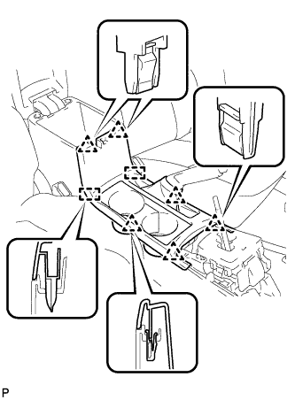
| 48. INSTALL UPPER CONSOLE PANEL SUB-ASSEMBLY (for Rear Disc Brake) |
Engage the 6 clips and 2 guides to install the upper console panel sub-assembly.
 |
| 49. INSTALL CENTER NO. 1 INSTRUMENT CLUSTER FINISH PANEL ASSEMBLY (for Rear Disc Brake) |
- HINT:
- for Manual Transaxle (Click here)
- for Automatic Transaxle (Click here)
| 50. INSTALL SHIFT LEVER KNOB SUB-ASSEMBLY (for Rear Disc Brake) |
- HINT:
- for Manual Transaxle (Click here)
- for Automatic Transaxle (Click here)
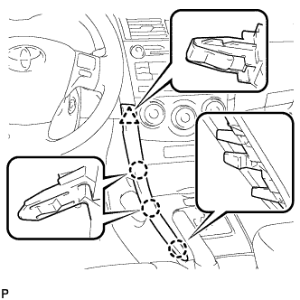
| 51. INSTALL LOWER INSTRUMENT PANEL FINISH PANEL LH (for Rear Disc Brake) |
Engage the 3 claws and clip, and then install the lower instrument panel finish panel LH.
 |
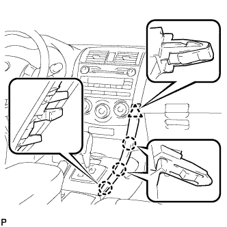
| 52. INSTALL LOWER INSTRUMENT PANEL FINISH PANEL RH (for Rear Disc Brake) |
Engage the 3 claws and clip, and then install the lower instrument panel finish panel RH.
 |
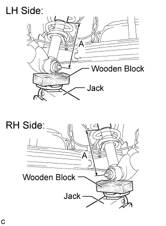
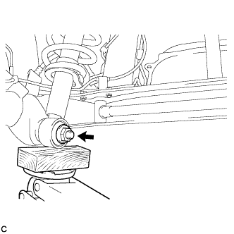
| 53. STABILIZE SUSPENSION |
Lower the vehicle.
Bounce the vehicle up and down several times to stabilize the suspension.
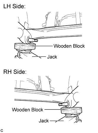
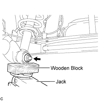
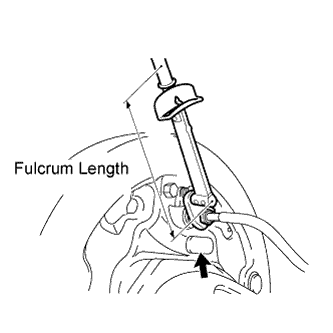
Jack up the rear axle beam, placing a wooden block underneath to avoid damage. Apply load to the suspension so that the rear shock absorber with coil spring is positioned as shown in the illustration.
- Length A:
- 206 mm (8.11 in.)
- CAUTION:
- Do not jack up the rear axle beam too high as the vehicle may fall.
 |
| 54. FULLY TIGHTEN REAR AXLE BEAM ASSEMBLY |
Fully tighten the 2 bolts on the rear axle beam assembly.
- Torque:
- 85 N*m{ 867 kgf*cm , 63 ft.*lbf }
- NOTICE:
- Since stopper nuts are used, tighten the bolts.
- The final torque must be applied under standard vehicle height conditions.
|
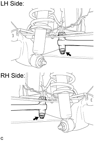
| 55. FULLY TIGHTEN REAR SHOCK ABSORBER WITH COIL SPRING LH |
Fully tighten the nut on the rear shock absorber with coil spring LH (lower side).
- Torque:
- 80 N*m{ 816 kgf*cm , 59 ft.*lbf }
- CAUTION:
- The final torque must be applied under standard vehicle height conditions.
 |
| 56. FULLY TIGHTEN REAR SHOCK ABSORBER WITH COIL SPRING RH |
- HINT:
- Perform the same procedure as the LH side.
| 57. INSPECT REAR WHEEL ALIGNMENT |
| 58. PLACE FRONT WHEELS FACING STRAIGHT AHEAD (w/ VSC) |
| 59. DISCONNECT CABLE FROM NEGATIVE BATTERY TERMINAL (w/ VSC) |
- NOTICE:
- Disconnect the cable from the negative (-) battery terminal for more than 2 seconds.
| 60. CONNECT CABLE TO NEGATIVE BATTERY TERMINAL (w/ VSC) |
| 61. PERFORM YAW RATE SENSOR ZERO POINT CALIBRATION (w/ VSC) |
| 62. CHECK STEERING ANGLE SENSOR ZERO POINT CALIBRATION (w/ VSC) |
| 63. CHECK FOR SPEED SENSOR SIGNAL (w/ ABS) |
| 64. CHECK FOR SPEED SENSOR SIGNAL (w/ VSC) |